CEB Press/Manufacturing Instructions/Arms - primary: Difference between revisions
Jump to navigation
Jump to search
No edit summary |
|||
| Line 29: | Line 29: | ||
Punch the holes on the 4" side of the angle iron first, all of them 1 1/4" from the edge of it. | Punch the holes on the 4" side of the angle iron first, all of them 1 1/4" from the edge of it. | ||
* The 3/4" holes are located 2" and 70" from one end of the angle iron. The two arms will be mirror images of one another. (These holes are slightly smaller than the others to minimize play between the primary and secondary arms, preventing extra vibrations on the frame.) | * The 3/4" holes are located 2" and 70" from one end of the angle iron. The two arms will be mirror images of one another. (These holes are slightly smaller than the others to minimize play between the primary and secondary arms, preventing extra vibrations on the frame.) | ||
*The 13/16" hole centers are located at 15", 31", 37", 39 5/8", 48 3/8", | *The 13/16" hole centers are located at 15", 31", 37", 39 5/8", 48 3/8", 51", and 64" from one end of the angle iron. Make the two arms mirror images of one another. | ||
*Determine which one is the right arm, and which is the left by looking at the model and label them. | *Determine which one is the right arm, and which is the left by looking at the model and label them. | ||
Then punch the holes in the right arm for the plates. The holes for the grate mounts will be torched later. | Then punch the holes in the right arm for the plates. The holes for the grate mounts will be torched later. | ||
*These hole locations are all 1 3/4" away from the edge of the iron, and their diameters are 13/16". | *These hole locations are all 1 3/4" away from the edge of the iron, and their diameters are 13/16". | ||
*They should be 9", 13", 18", and 28" from the end when the arm is in the right position (see model). | *They should be 9", 13", 18", and 28" from the end when the arm is in the right position (see model). | ||
Revision as of 05:29, 22 September 2011
| |||||||||||||||||||||||||
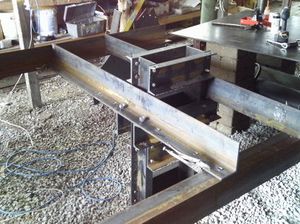
The primary arms attach the cylinder/frame assembly to the secondary arms, which support it. They also attach to the Brickholder plate, the Dirt-keeper plate, the Controller Mount, and the Valve Mount.
Tools Required
Hole punch with 13/16" and 3/4" dies
Materials Required
- 2 pieces 72" long - 4"x6"x1/2" angle steel
Diagrams
Left
Right
Fabrication Steps
Punch the holes on the 4" side of the angle iron first, all of them 1 1/4" from the edge of it.
- The 3/4" holes are located 2" and 70" from one end of the angle iron. The two arms will be mirror images of one another. (These holes are slightly smaller than the others to minimize play between the primary and secondary arms, preventing extra vibrations on the frame.)
- The 13/16" hole centers are located at 15", 31", 37", 39 5/8", 48 3/8", 51", and 64" from one end of the angle iron. Make the two arms mirror images of one another.
- Determine which one is the right arm, and which is the left by looking at the model and label them.
Then punch the holes in the right arm for the plates. The holes for the grate mounts will be torched later.
- These hole locations are all 1 3/4" away from the edge of the iron, and their diameters are 13/16".
- They should be 9", 13", 18", and 28" from the end when the arm is in the right position (see model).
