CEB Press/Manufacturing Instructions/Arms - primary
| |||||||||||||||||||||||||
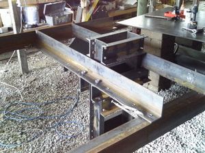
The primary arms attach the cylinder/frame assembly to the secondary arms, which support it. They also attach to the Brickholder plate, the Dirt-keeper plate, the Controller Mount, and the Valve Mount.
Tools Required
Hole punch with 13/16" and 3/4" dies
Materials Required
- 2 pieces 72" long - 4"x6"x1/2" angle steel
Diagrams
Left
Right
shonda's print for the Super CEB
Fabrication Steps
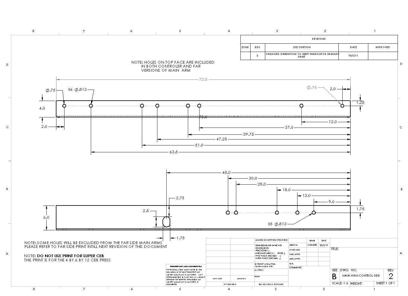
There are two primary arms, one from each 6' (72”) piece of angle steel; one will serve as the left arm, the other as the right arm. The arms will not be identical, as the left arm will have no holes punched on the 6” side whereas the other arm will need holes punched on the 6” side. On the six-foot piece of angle steel to become the left arm, you need to punch the following holes, each centered 1 1/4” from the long edge on the 4” inch side of the angle steel:
- Two total 3/4” diameter holes at 2” and 70” (or 2” measured from the right edge) from the left end of the angle steel.
- Seven total 13/16” diameter holes at 15”, 31”, 37”, 39 3/4”, 48 1/4” (23 3/4” measured from the right), 51” (21” from the right) and 64” (8” from the right) from the left end of the angle steel.
On the right arm, repeat all of the hole punches (the two 3/4” and the seven 13/16”) on the four-inch side of the angle iron. Additionally, punch the following holes on the 6” side of the angle iron for the Right Primary Arm, each centered 1 3/4” from the long edge:
- Four total 13/16” diameter holes at 9”, 13”, 18”, and 28” inches, each measured from the left side of the angle iron.

