CEB Press/Manufacturing Instructions/Hopper supports: Difference between revisions
Jump to navigation
Jump to search
No edit summary |
|||
| (4 intermediate revisions by the same user not shown) | |||
| Line 13: | Line 13: | ||
== Diagrams == | == Diagrams == | ||
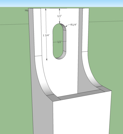
[[Image:hoppersupcut.png|thumb|right|400px|The cutaway at the top of the hopper supports.]] | |||
<html> | <html><iframe src="http://sketchup.google.com/3dwarehouse/mini?mid=e4c762d16d8f60401211da1f85706ccd&etyp=sw&width=400&height=300" frameborder="0" scrolling="no" marginheight="0" marginwidth="0" width="400" height="300"></iframe> | ||
<iframe src="http://sketchup.google.com/3dwarehouse/mini?mid= | |||
</html> | </html> | ||
== Fabrication Steps == | == Fabrication Steps == | ||
| Line 23: | Line 21: | ||
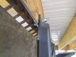
[[Image:shakerbolt.png|thumb|left|The bolts in the shaker.]] | [[Image:shakerbolt.png|thumb|left|The bolts in the shaker.]] | ||
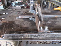
[[Image:supportbolts.jpg|thumb|200px|The shaker in place, ready to weld.]] | [[Image:supportbolts.jpg|thumb|200px|The shaker in place, ready to weld.]] | ||
#Torch the necessary areas | #Torch away the necessary areas. See Diagrams. | ||
#*The holes for the hopper mounting need to be | #*The holes for the hopper mounting need to be 28" away from the bottom side. Mark 28" on the opposite tubing walls and torch 1/2" holes. Insure a 1/2" bolt goes all the way thru. | ||
#* | #*Torch the cutaway at the top and the slot. | ||
#Grind away any slag. | #Grind away any slag. | ||
#Lay one support on the table, with the grate mount hole touching the table. | #Lay one support on the table, with the grate mount hole touching the table. | ||
#Tighten 3/4" bolts with nuts to the [[CEB Press/Manufacturing Instructions/Soil Shaker|Soil Shaker]] so the bolt head is where the hammer will be. | #Tighten 3/4" bolts with nuts to the [[CEB Press/Manufacturing Instructions/Soil Shaker|Soil Shaker]] so the bolt head is where the hammer will be. | ||
#Prop this up on the leg, so the first bolt is 2" above the | #Prop this up on the leg, so the first bolt is about 2" above the 28" hole both bolts are touching the support. | ||
#Mark which side of the shaker you are welding the bolts for. | #Mark which side of the shaker you are welding the bolts for. | ||
#Tack the bolts in place, remove the nuts and dismount the shaker. | #Tack the bolts in place, remove the nuts and dismount the shaker. | ||
#Protect the threads, and finish welding the bolts to the support. | #Protect the threads, and finish welding the bolts to the support. | ||
#*You are only doing this on one of the supports, the other side, you will do in place, so the spacing is correct. | #*You are only doing this on one of the supports, the other side, you will do in place, so the spacing is correct. | ||
Latest revision as of 23:57, 13 December 2011
| |||||||||||||||||||||||||
![]() Warning: The documentation for the CEB Press is undergoing a thorough overhaul. CAD models and written directions are presently obsolete. For more information, see Talk:CEB_Press#Documentation_overhaul_in_progress. When the models, specifications and text on this article have been thoroughly reviewed, updated when necessary, and confirmed as whole and accurate, this warning may be removed.
Warning: The documentation for the CEB Press is undergoing a thorough overhaul. CAD models and written directions are presently obsolete. For more information, see Talk:CEB_Press#Documentation_overhaul_in_progress. When the models, specifications and text on this article have been thoroughly reviewed, updated when necessary, and confirmed as whole and accurate, this warning may be removed.
The hopper supports attach to the hopper, and attaches to the main frame via leg holders. They also hold the Soil Shaker
Tools Required
- Torch
- Welder
Materials Required
- 2 pieces 48" long - 1/4”x2”x2” tubing
- Soil Shaker (this should be dis-assembled, although you can do it assembled, its just heavier and more difficult to manouver.)
- 3/4"x1 1/2" bolts (2)
Diagrams
Fabrication Steps
- Torch away the necessary areas. See Diagrams.
- The holes for the hopper mounting need to be 28" away from the bottom side. Mark 28" on the opposite tubing walls and torch 1/2" holes. Insure a 1/2" bolt goes all the way thru.
- Torch the cutaway at the top and the slot.
- Grind away any slag.
- Lay one support on the table, with the grate mount hole touching the table.
- Tighten 3/4" bolts with nuts to the Soil Shaker so the bolt head is where the hammer will be.
- Prop this up on the leg, so the first bolt is about 2" above the 28" hole both bolts are touching the support.
- Mark which side of the shaker you are welding the bolts for.
- Tack the bolts in place, remove the nuts and dismount the shaker.
- Protect the threads, and finish welding the bolts to the support.
- You are only doing this on one of the supports, the other side, you will do in place, so the spacing is correct.


