CEB Press/Manufacturing Instructions/Roller guides: Difference between revisions
Jump to navigation
Jump to search
| (10 intermediate revisions by 5 users not shown) | |||
| Line 1: | Line 1: | ||
{{Template:CEB Press Manufacturing Instructions Navbox}} | {{Template:CEB Press Manufacturing Instructions Navbox}} | ||
[[Image:roller-guides.jpg|thumb]] | [[Image:roller-guides.jpg|thumb]] | ||
[[Image:new-roller-guides.jpg|thumb]] | |||
{{Warning|The documentation for the CEB Press is undergoing a thorough overhaul. CAD models and written directions are presently obsolete. For more information, see [[Talk:CEB_Press#Documentation_overhaul_in_progress]]. When the models, specifications and text on this article have been thoroughly reviewed, updated when necessary, and confirmed as whole and accurate, this warning may be removed.}} | |||
See also [[CEB Press/Bill of Materials]] | See also [[CEB Press/Bill of Materials]] | ||
== Tools Required == | == Tools Required == | ||
*Hole punch or drill with 1/2” bit | *Hole punch or drill with 1/2” bit | ||
| Line 12: | Line 15: | ||
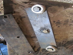
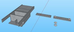
You need 2 roller guides. Each one requires the following: | You need 2 roller guides. Each one requires the following: | ||
===Steel | ===Steel=== | ||
*1/ | *1/2”x3”x16” plate (1) | ||
*Spacer plate (1) (One roller guide will use a 3/8" thick plate, and the other will use a 1/2" plate)(these can be scrap, but need to be smaller than 3”x9.5”) | *Spacer plate (1) (One roller guide will use a 3/8" thick plate, and the other will use a 1/2" plate)(these can be scrap, but need to be smaller than 3”x9.5”) | ||
===Bolts | ===Bolts=== | ||
*1/2”x2” bolt (1) | *1/2”x2” bolt (1) | ||
*12mm x 50mm bolts (2) | *12mm x 50mm bolts (2) | ||
===Nuts | ===Nuts=== | ||
*1/2” nut (1) | *1/2” nut (1) | ||
*12mm nuts (2) | *12mm nuts (2) | ||
===Washers | ===Washers=== | ||
*1/2” washer (1) | *1/2” washer (1) | ||
*1/2” lock washer (1) | *1/2” lock washer (1) | ||
*12mm lock washers (4) | *12mm lock washers (4) | ||
===Bearings | ===Bearings=== | ||
* V Groove bearing 12mm [http://www.vxb.com/page/bearings/PROD/Kit8406 Buy] | * V Groove bearing 12mm [http://www.vxb.com/page/bearings/PROD/Kit8406 Buy] | ||
| Line 37: | Line 40: | ||
[[Image:RollerGuideExploded.jpg|500px]] | [[Image:RollerGuideExploded.jpg|500px]] | ||
[[Image:RollerGuideCollapsed.jpg|500px]] | [[Image:RollerGuideCollapsed.jpg|500px]] | ||
[http://sketchup.google.com/3dwarehouse/details?mid=84fd682fbec88d49b38804396e417a9b sketchup file] | |||
== Fabrication Steps == | == Fabrication Steps == | ||
===Main plate | ===Main plate=== | ||
*Punch 1/2” diameter holes in 1/ | *Punch 1/2” diameter holes in 1/2”x3”x16” plate. (3 holes) See diagram. | ||
*Put 1/2” bolt thru the center hole and weld it in place. | *Put 1/2” bolt thru the center hole and weld it in place. | ||
===Spacer plates | ===Spacer plates=== | ||
*Punch a hole for the bolt welded to main plate. This should be centered horizontally, and placed vertically so that the plate doesn't stick out from the main plate. | *Punch a hole for the bolt welded to main plate. This should be centered horizontally, and placed vertically so that the spacer plate doesn't stick out from the main plate. | ||
===12mm bolts | ===12mm bolts=== | ||
*Grind off the top of the bolts so that the head is 1/4” thick or less. (This is so that the bolts will not be touching the drawer as it slides in and out.) | *Grind off the top of the bolts so that the head is 1/4” thick or less. (This is so that the bolts will not be touching the drawer as it slides in and out.) | ||
===Assembly | ===Assembly=== | ||
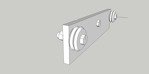
*On the 12mm bolts, place, in the following order, the V groove bearings, one lock washer, the main plate, one lock washer, the 12mm nut. The bearings should be on the side of the 1/2” bolt head. | *On the 12mm bolts, place, in the following order, the V groove bearings, one lock washer, the main plate, one lock washer, the 12mm nut. The bearings should be on the side of the 1/2” bolt head. | ||
*Place one of these on each end of the main plate. | *Place one of these on each end of the main plate. | ||
*Tighten them down. | *Tighten them down. | ||
*On the side with the 1/2” bolt threads, place the spacer plate** on the bolt. | *On the side with the 1/2” bolt threads, place the spacer plate** on the bolt. | ||
**The two roller guides will be identical, except for that one will have a 1/2” spacer plate, and the other will have a 3/8” spacer plate (this is to properly space the guides to the rails on the drawers). | |||
[[Category:CEB Press]] | |||
Latest revision as of 02:16, 13 December 2011
| |||||||||||||||||||||||||
![]() Warning: The documentation for the CEB Press is undergoing a thorough overhaul. CAD models and written directions are presently obsolete. For more information, see Talk:CEB_Press#Documentation_overhaul_in_progress. When the models, specifications and text on this article have been thoroughly reviewed, updated when necessary, and confirmed as whole and accurate, this warning may be removed.
Warning: The documentation for the CEB Press is undergoing a thorough overhaul. CAD models and written directions are presently obsolete. For more information, see Talk:CEB_Press#Documentation_overhaul_in_progress. When the models, specifications and text on this article have been thoroughly reviewed, updated when necessary, and confirmed as whole and accurate, this warning may be removed.
See also CEB Press/Bill of Materials
Tools Required
- Hole punch or drill with 1/2” bit
- Welder
- Angle Grinder
Materials Required
You need 2 roller guides. Each one requires the following:
Steel
- 1/2”x3”x16” plate (1)
- Spacer plate (1) (One roller guide will use a 3/8" thick plate, and the other will use a 1/2" plate)(these can be scrap, but need to be smaller than 3”x9.5”)
Bolts
- 1/2”x2” bolt (1)
- 12mm x 50mm bolts (2)
Nuts
- 1/2” nut (1)
- 12mm nuts (2)
Washers
- 1/2” washer (1)
- 1/2” lock washer (1)
- 12mm lock washers (4)
Bearings
- V Groove bearing 12mm Buy
Diagrams
Fabrication Steps
Main plate
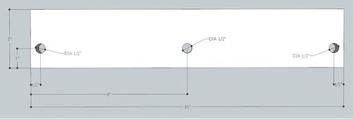
- Punch 1/2” diameter holes in 1/2”x3”x16” plate. (3 holes) See diagram.
- Put 1/2” bolt thru the center hole and weld it in place.
Spacer plates
- Punch a hole for the bolt welded to main plate. This should be centered horizontally, and placed vertically so that the spacer plate doesn't stick out from the main plate.
12mm bolts
- Grind off the top of the bolts so that the head is 1/4” thick or less. (This is so that the bolts will not be touching the drawer as it slides in and out.)
Assembly
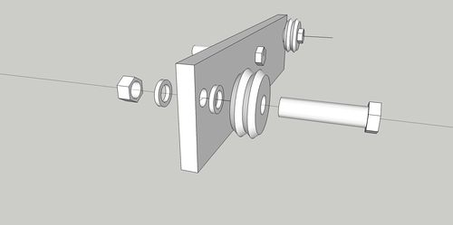
- On the 12mm bolts, place, in the following order, the V groove bearings, one lock washer, the main plate, one lock washer, the 12mm nut. The bearings should be on the side of the 1/2” bolt head.
- Place one of these on each end of the main plate.
- Tighten them down.
- On the side with the 1/2” bolt threads, place the spacer plate** on the bolt.
- The two roller guides will be identical, except for that one will have a 1/2” spacer plate, and the other will have a 3/8” spacer plate (this is to properly space the guides to the rails on the drawers).
