CEB Press/Manufacturing Instructions/Soil Shaker: Difference between revisions
Jump to navigation
Jump to search
| Line 30: | Line 30: | ||
== Fabrication Steps == | == Fabrication Steps == | ||
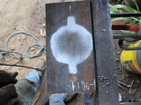
[[Image:motorholeceb.jpg|thumb| | [[Image:motorholeceb.jpg|thumb|200px|Marking the hole for the shaker motor.]] | ||
#Torch a hole for mounting the motor. | #Torch a hole for mounting the motor in the 8" piece of 4x4 angle. | ||
#*The center of the hole should be 1 3/4" away from the corner of the angle. | #*The center of the hole should be 1 3/4" away from the corner of the angle. | ||
#*You need to ensure the hole is large enough so that where the bolt holes are will be touching the angle when in place. The motor is most likely raised in the center. | #*You need to ensure the hole is large enough so that where the bolt holes are will be touching the angle when in place. The motor is most likely raised in the center. | ||
#*You can torch separate holes for the bolts, or do one large, odd shaped one like is pictured. | #*You can torch separate holes for the bolts, or do one large, odd shaped one like is pictured. | ||
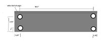
#Punch the 13/16" holes in the 21" angle for mounting. These should be 18.5" apart, center to center. You may need to torch the two on top. | |||
[[Image:shakermountholes.jpg|thumb|left|200px|The mount hole locations, please redo]] | |||
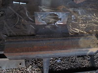
#Weld the two angle pieces together as pictured, ensuring they are perfectly flush and square. Skip around while welding so it doesn't warp one way or another. | |||
[[Image:weldedangles.jpg|thumb|right|200px|Welding the pieces together.]] | |||
#Grind off the center of the weld on the top side, where the pillow bearing will go. | |||
#Mark the hole locations for the pillow bearings and where to drill the coupler. | |||
#*Bolt the motor in place, and couple the rod to it, so the rod is touching the shaft. | |||
#*Slide the pillow bearings up the shaft so the first one is about 3/16" away from the coupler. The other should be about 1/8" away from the end of the material. | |||
#*Spray mark thru the holes where to torch. | |||
#*Mark on the shaft where it goes into the coupler, You'll need this so you can drill thru the coupler and shaft for a pin to link the two. | |||
#Disassemble the motor from the frame. | |||
#Torch the other holes and grind away their slag. | |||
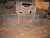
#Weld the Braces onto the underside of the frame (NOT like in the model, like in the photo.) | |||
[[Image:weldbraces.jpg|thumb|left|200px|Welding the braces together.]] | |||
#Drill the 3/8" hole thru the coupler and rod, using the mark you made to make sure the rod is in the proper amount. | |||
#*Drill thru both at the same time. You will need some sort of vice to hold it down while you drill. | |||
#*Double check that your bolt will fit thru. If not, either re-drill it with a slightly bigger bit, or do another set of holes. | |||
Revision as of 01:12, 27 September 2011
| |||||||||||||||||||||||||
![]() Warning: The documentation for the CEB Press is undergoing a thorough overhaul. CAD models and written directions are presently obsolete. For more information, see Talk:CEB_Press#Documentation_overhaul_in_progress. When the models, specifications and text on this article have been thoroughly reviewed, updated when necessary, and confirmed as whole and accurate, this warning may be removed.
Warning: The documentation for the CEB Press is undergoing a thorough overhaul. CAD models and written directions are presently obsolete. For more information, see Talk:CEB_Press#Documentation_overhaul_in_progress. When the models, specifications and text on this article have been thoroughly reviewed, updated when necessary, and confirmed as whole and accurate, this warning may be removed.
Tools Required
Materials Required
Steel
- 4"x4"x1/2" Angle:
- 8" Piece: Motor attachment
- 21" Piece: Hopper attachment
- 1" Rebar: 8.5" (2): Braces
- 1" DOM Roundstock: 6.5", shaft
- 1"x2" flatbar: 11"
Other
- 1"x2"x5" eccentric pillow bearings with locking eccentrics.
- 1" to 1" coupler to fit motor
- 1/4"x2.5" or 3/8"x2.5" bolt and accompanying nut.
- Hydraulic motor (find specs)
Diagrams
Fabrication Steps
- Torch a hole for mounting the motor in the 8" piece of 4x4 angle.
- The center of the hole should be 1 3/4" away from the corner of the angle.
- You need to ensure the hole is large enough so that where the bolt holes are will be touching the angle when in place. The motor is most likely raised in the center.
- You can torch separate holes for the bolts, or do one large, odd shaped one like is pictured.
- Punch the 13/16" holes in the 21" angle for mounting. These should be 18.5" apart, center to center. You may need to torch the two on top.
- Weld the two angle pieces together as pictured, ensuring they are perfectly flush and square. Skip around while welding so it doesn't warp one way or another.
- Grind off the center of the weld on the top side, where the pillow bearing will go.
- Mark the hole locations for the pillow bearings and where to drill the coupler.
- Bolt the motor in place, and couple the rod to it, so the rod is touching the shaft.
- Slide the pillow bearings up the shaft so the first one is about 3/16" away from the coupler. The other should be about 1/8" away from the end of the material.
- Spray mark thru the holes where to torch.
- Mark on the shaft where it goes into the coupler, You'll need this so you can drill thru the coupler and shaft for a pin to link the two.
- Disassemble the motor from the frame.
- Torch the other holes and grind away their slag.
- Weld the Braces onto the underside of the frame (NOT like in the model, like in the photo.)
- Drill the 3/8" hole thru the coupler and rod, using the mark you made to make sure the rod is in the proper amount.
- Drill thru both at the same time. You will need some sort of vice to hold it down while you drill.
- Double check that your bolt will fit thru. If not, either re-drill it with a slightly bigger bit, or do another set of holes.


