CEB Press/Manufacturing Instructions/Frame with main cylinder
| |||||||||||||||||||||||||
![]() Warning: The documentation for the CEB Press is undergoing a thorough overhaul. CAD models and written directions are presently obsolete. For more information, see Talk:CEB_Press#Documentation_overhaul_in_progress. When the models, specifications and text on this article have been thoroughly reviewed, updated when necessary, and confirmed as whole and accurate, this warning may be removed.
Warning: The documentation for the CEB Press is undergoing a thorough overhaul. CAD models and written directions are presently obsolete. For more information, see Talk:CEB_Press#Documentation_overhaul_in_progress. When the models, specifications and text on this article have been thoroughly reviewed, updated when necessary, and confirmed as whole and accurate, this warning may be removed.
Tools Required
- Torch
- Hole Punch
- Mag Drill
- 1/2” Allen Wrench
Materials Required
- The prepared main cylinder
- All of the components in Main Frame Preparation
- Leg Holders (2)
Steel
- 6” Heavy (7/16”) U-Channel: (26" for monster, 18" for normal)
- (13” for Monster)(9" for normal)(2); Spacers
- 2"x2"x1/4" Angle: 12"; Dirt Blockers: 6” (2)
- 1 1/2” DOM Roundstock: 8 1/2”; Cylinder Pin (1)
- 1 1/2” Inter Diameter DOM Tubing: 2 1/2"; Pin Receptors:1 1/4” (2)
- For Optional “Jig”: 6”x12” Tubing: 52”
Nuts and Bolts
- 3/4”x1.5” Bolts (28 normal, 32 super)
- Horizontal members (16)
- Drawer members (8)
- Wide cylinder supports (4 normal, 8 super)
- 3/4” Steel Nuts (2): Thin cylinder supports
- 3/4” Galvanized Nuts (30 normal, 34 super)
- Horizontal members (16)
- Drawer members (8)
- Wide cylinder supports (4 normal, 8 super)
- Thin cylinder supports: (2)
Diagrams
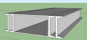
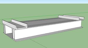
(model not completely done)
Assembly
Step 1: Mag Drill Holes in Verticals.
- Gather materials for the “Jig”; this means 6”x12” tubing (52”) and any extra heavy U Channel. If you don't have any laying around, you can use one drawer member, and one spacer on each side.
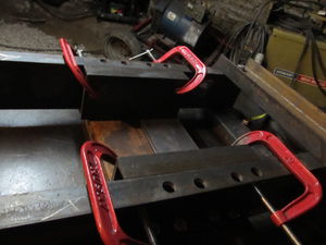
- Clamp the vertical pieces to the "Jig" on each end, with extra U channel in between the tubing and the vertical pieces. See the diagram on the right. Insure the two verticals are flush at the top end (the one with the roller slots). The slots and the thin cylinder support holes will need to align in the proper places with the cylinder later.
- Clamp one horizontal member at each end of the jig. Make sure it is flush with the ends of the verticals.
- Ensure they are square with the jig by using a large square
- Clamp using 1 or 2 vise grips on either side.
- Transfer Punch thru the holes on the horizontal members (B).
![]() Hint: It really helps to label each piece before taking it apart, so that if you end up unbolting the piece later, you'll know exactly where it goes and in what orientation. Mark which side will be the top of the machine.
Hint: It really helps to label each piece before taking it apart, so that if you end up unbolting the piece later, you'll know exactly where it goes and in what orientation. Mark which side will be the top of the machine.
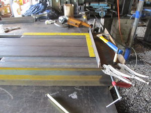
- Mark where the edge of the horizontal member is in relation to the vertical members on the vertical member. Use a square to mark the same location on the opposite side. Do this on all four locations. See image.
- Remove the horizontal members.
- Use a Mag-Drill to drill 3/4" holes in each spot you transfer punched.
- Flip the jig over so you have access to drill the other holes. See video for help.
- Align the other horizontal members with the marks you previously made, and insure once more that they are square.
- If it is on the mark on each side, but not square, just get it as close as you can to the marks while insuring it is square.
- Clamp the members in place.
- Transfer punch them.
- Remove them.
- Mag Drill them.
- Unclamp the verticals from the jig.
Step 2: Assemble top/bottom
- Loosely bolt the crossmembers on one side in place.
- Square them up with the verticals using a large square.
- If they're not lining up properly square it up on what you labeled top first and tighten those bolts. Then square out the other side and torch out any spots prohibiting the bolts from going thru.
- Tighten all of those bolts.
- Flip over the frame.
- Loosely bolt the crossmembers on this side and square them. Insure the members on the other side are level with this one.
- Tighten these bolts.
Step 3: Mag-Drill the holes for the wide cylinder supports and drawer members
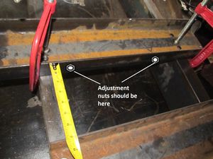
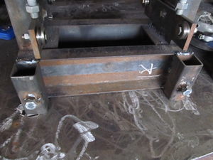
- Clamp the drawer member centered, (5" for standard CEB, 7" for the "super" CEB) from the upper cross member. The drawer slots should be on this side, not opposite. Make sure the nuts are facing where the drawer was, look at the picture.
- Clamp the wide cylinder support directly below it. Make sure you mark where each one goes.
- Transfer punch thru those holes.
- Mag-Drill 1" holes at these centers.
- Flip the frame over and do the same thing on the other side.
Step 4: Tack the spacers
Note: You are only tacking them because when you stretch the frame, it may "move" their location. The spacers need to be contacting the drawer when you are pressing bricks, or the top edges of the bricks will be "fuzzy." See the quality control section below for more info.
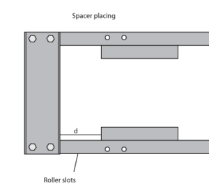
- With the frame laid down, and one of the drawer members in place, place the spacers (U-channel, 13" for monster and 9" for normal) on each side. The end of them is to be "d" (7 1/16" for monster)(5 1/16" for normal) away from the upper cross member. Look at the diagram./
- Insure they are parallel with the U-channel and C-clamp in two places for each.
- Tack them on this side in 3 spots. You may need to grind this off later, so make sure the tacks aren't longer than 1/4" or so.
- Flip over the frame and tack the other side.
Step 5: Weld the dirt blockers
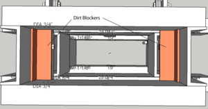
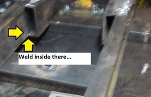
- Put the dirt blockers in place, between the vertical members, so the bottom side of them is about 1/8" above the bottom of the upper crossmembers.
- Weld the portion inside of the vertical members, taking care to not weld it to the crossmembers.
Step 6: Fit the main cylinder
For more info, see the video. Also, there's a page on Make Projects that has more photos with the same instructions.
- Lay the frame down, with all of the crossmembers and drawer members in place except the upper crossmember and drawer member which are facing up.
- Place the assembled cylinder lying down so that the press feet are between the spacers.
- The cylinder needs to be fully extended for this step. See "Attach them to the cylinder" earlier on this page for how to do this.
- You need to insure that the vertical height is correct, and that the cylinder is centered. The top of the upper press foot should be (4 3/4" for the regular CEB, and 6 3/4" for the "super" CEB) away from the bottom of the upper crossmembers.
- Add a 1/8" spacer (big washers work great) under the cylinder, where it contacts the lower crossmember. This insures the cylinder is centered vertically.
- Use spray paint to mark the location of the tubing on the crossmember.
- Place the other upper crossmember in place, putting bolts thru the holes.
- Use spray paint to mark the location of the tubing on the crossmember.
- Remove this member and move the cylinder out of the way of the other.
- Place one of the DOM tubing pieces in the center of each of the sprayed marks and spray paint around this to mark where you will torch.
- Torch around the outside of the ring left by the DOM tubing.
- Insure the tubing will go thru each hole. If not, retorch it. Grind off the slag.
- Lay the cylinder back down and replace the top crossmember. Place the tubing in the torched holes.
- Insure the pin will go thru the tubing and the cylinder. If not, retorch the holes so that it will.
- With the pin held in, weld the tubing on the top in place (Youll want to tack it in many places before welding around it.). Then tack it as best you can on the back by hanging the frame off of the table and overhead welding.
- Remove cylinder and pin, as well as the two crossmembers.
- Fully weld the tubing on both sides. Jump around a lot to minimize any warping on the tube. Block the insides of the tubing so no spatter goes inside.
- Replace the crossmembers and the cylinder. Insure the pin still fits and hammer it thru.
Step 7: Fit the thin cylinder spacers
- Verify that the hole for the cylinder spacers is at the right height.
- Do so by putting the 6" bolts thru those holes and putting the spacer onto it. It should fit on the lip of the cylinder as shown.
- If not, torch out where needs to be changed.
- Weld the nuts for them in place on the inside of the frame. Protect the threads.
Step 8: Stretch the frame
See the video.
Note: you need a hydraulic pump for this step.
- Attach the cylinder to a hydraulic pump or power cube and contract the cylinder at least 1".
- Stand up the frame so the press feet are facing down.
- Insert the Soil loading drawer on top of the horizontal members so that the press plate is facing the press feet.
- If the drawer doesn't fit because of the spacers, you welded them too close. Grind them off and weld them a little higher.
- Position the drawer so that the press plate will be fully contacted by the press feet.
- Bolt the drawer members on snugly.
- Use the pump to expand the cylinder as much as possible. The pump will likely stall out.
- If the pump stalls, turn it back on and expand it fully once more.
- Expand at least 3 times.
- Contract it, so you can weld the spacers in. Then detach from the pump.
Observations
- Remove the drawer members
- Look where the spacers are near the drawer. The spacers should be very close to the drawer.(less than 1/32"). See quality control below if you wonder why.
- If they are too far, grind off the welds and position them so they are contacting the drawer. Yet again, make sure they are perfectly square with the verticals.
- Replace one drawer member and lay the frame back down on top of this drawer member.
Step 9: Weld the spacers
- Protect the drawer member on the bottom and the press foot so that when you weld, spatter won't stick. You could use some piece of metal or a nonflammable cloth.
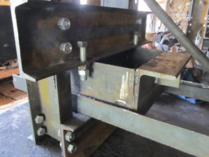
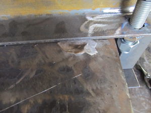
- On the inside, bottom edge, weld the interior of the spacer inwards as far as you can. This should be an inch or more. Do this in all 4 corners accessable from this side of the frame. See the photo.
- Weld the top 100%.
- Grind the top weld flush with the U-channel.
- Loosely bolt the other drawer member in place.
- Flip over the frame.
- Remove the other drawer member, and repeat steps 1-5.
Step 10:Fit the drawer members
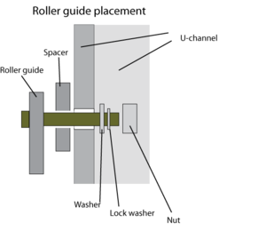
- Install the Roller guides as shown in the illustration. One side should have a 1/2" spacer, and the other should have a 3/8" spacer plate. Tighten the bolt snug, but so that it can still move up and down.
- Replace the drawer as if you're going to stretch the cylinder again. Consult the photo above.
- Make sure the drawer members are loose to do so. You may need to hold them upwards as you push the drawer in.
- Make sure the rails slide on the roller guides. You can check by putting bolts thru the nuts and making sure they have a lot of contact with the roller guides.
- Adjust the drawer members horizontally so the roller adjustment nuts welded to them are centered on the roller guides.
- Finger tighten the bolts on the drawer members, as they are sitting on top of the drawer.
- Try to slide the drawer in and out.
- If the drawer gets stuck somewhere, investigate and find where it's hitting.
- You'll probably need to loosen one of the drawer members and move it up a bit. This can be done uniformly using cardboard shims. See photo.
- Place the shim between the drawer and the crossmember. Tighten the bolts again. Remove the shims by "jiggling" the drawer.
- If it's hitting a spacer, grind down the spacer.
- If the drawer itself is prohibitive in some spots, it wasn't grinded evenly. grind down the high spots.
- Once the drawer is properly adjusted, tighten these bolts all the way.
Step 11:Install the remaining pieces
- Install the magnet holder onto the press foot. Make sure it's got an extra nut on it so you can lock its position. The flatbar needs to be parallel with the verticals. Lock it down with the nut.
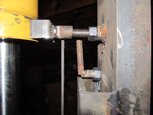
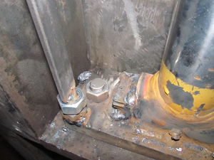
- Install the thin cylinder supports by screwing the bolt in with an extra nut on it as shown, and placing the u-channel against the cylinder. Get both of them snug so the cylinder is centered with pressure on each side. Tighten down the nut to lock it.
- Install the sensor holder so the end of it (the furthest part from bolt) is overlapping the path of the magnet holder.
- Bolt the wide cylinder supports to the frame. Put a 2" bolt with an extra nut thru the nuts on the top of the supports. Tighten these down so the cylinder is centered with pressure on each side. Tighten down the nut to lock it.
Step 12:Tighten all bolts
- Go back thru the frame and make sure all of the bolts are tight (except the roller guide bolts, that will be done later.)
Step 13: Weld the leg holders to the frame.
Position them on the upper horizontal member on the non-ejector side(Opposite side of roller guide holes. Weld them to the horizontal members. Insure they are square in all directions.
Quality Control
- The press foot must fit tightly within the compression chamber. Otherwise, the corners of bricks will not be clean as soil escapes from the compression chamber.
- The compression chamber side spacers need to be even with the other sides of the chamber
- Main cylinder adjusters cannot push against the cylinder in their native position. They are used to adjust the cylinder by the action of the bolt.
- Here is a discussion:
Video Explantion
