Roberto Log
![]() Status - Done: Filament Extruder Assembly To Do: Visual diagrams and CAD files for all the needed parts Blocks: --
Status - Done: Filament Extruder Assembly To Do: Visual diagrams and CAD files for all the needed parts Blocks: --
Timesheet. Marcin Log. Israel Log. Ayo Log. Kassie Log. Dixon Log. Jozef Log. Abraham Log. Richard Log. Laszlo Log. Jean-Baptiste Log. Roberto Log. Abe Log. Emmanouil Log. Jose Log. Cedric Log. Michael Log. Frank Log. Calegtriminio_log.
D3D D3D_Meeting_Log D3D monday hangouts D3D network group D3D scrumy D3D_Part_Library D3D_Integration D3D_Development Wiki_Cheatsheet
Thu Jul 20, 2017
File:Filament Extruder Assembly.fcstd Added the Fan plus all the washers, nuts and bolts. Only missing wires, screws for Electronics, and the Welding Blanket. Also updated many files and pictures at the part library.(4 Hours)
Mon Jul 17, 2017
Today I tried to explain what I understand about File Simplification, because I see it is not clear enough. Link
Sat Jul 15, 2017
As I was all the day without internet, I worked offline on the File:Filament Extruder Assembly.fcstd. There were many things to fix and better detailed parts to add. Still are missing some washers, bolts and nuts for the Flange and motor and the detailed SSR.
Fry Jul 14, 2017
Today I followed the process on slide 3 in the working doc. Finished Fasteners and small parts visual diagram for the Big Box Enclosure module, including purchasing links, CAD Files and updated the Part Library and Master Index. Began a visual diagram for the Extruder-Auger-Flange module (slides 9-10) and coordinated with Dixon about what's next. I also asked Alejandro Calegtriminio_log to do a simplified CAD for File:46 Part 20b case.stl.
Thu Jul 13, 2017
I will focus on the visual diagram and CAD files for the non electronic parts in the Box and Extruder Module.
Tue Jul 11, 2017
Mon Jul 10, 2017
Lyman_Filament_Extruder_Part_Library#Assembled_Modules_Gallery
Sun Jul 09, 2017
File:Filament Extruder Assembly.fcstd
Sat Jul 08, 2017
Filament Extruder Assembly. Includes Bix Box Enclosure + Hopper + Extruder Barrel + Auger + Flange + Thermal Components.
Thu Jul 06, 2017
Mon Jul 03, 2017
File:Big Box Enclosure + Hopper.fcstd Final assembly with merged files.
The following files are duplicated and should be deleted:
- File:Case TL.fcstd
- File:Knob.fcstd
- File:Case BL.fcstd
- File:Corner Panel TR.fcstd
- File:Corner Panel TL.fcstd
- File:Corner Panel BL.fcstd
- File:Fan Bracket.fcstd
- File:Front Panel.fcstd
- File:Bottom Panel BL.fcstd
- File:Bottom Panel BR.fcstd
- File:Bottom Panel TL.fcstd
- File:Bottom Panel TR.fcstd
- File:Corner Panel + Hole.fcstd
- File:Side Panel R.fcstd
- File:Side Panel T.fcstd
- File:Side Panel L.fcstd
- File:Case BR.fcstd
- File:Case TR.fcstd
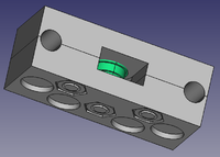
- File:Extruder Case.fcstd
- File:H Hopper.fcstd
Fry Jun 30, 2017
Thu Jun 23, 2017
Tue Jun 20, 2017
Sat May 27, 2017
File:Heated bed 01.fcstd FreeCAD source file.
Short_Idler_LAI Sample of finished LAI.
Script for getting an iso view:
- Install this Macro. How to install macros in FreeCAD.
- Open a FreeCAD file with the part you want to extract the isometric view from.(If the wanted part is separated in several smaller parts, go to Part Workbench, select all of those parts and use the tool "Make compound" in the top dropdown menu. In this video I used EPA Workbench for assembling the Universal Idler piece with 2 nuts, then I went to Part Workbench for making compound).
- Select the wanted part, by double clicking over it.
- Execute the Macro (Can take between 0 and 1.5 minutes)
- Double click in the new drawing page called "AutoDrawing".
- You can change position and scale for each drawing in the combo view data tab (after selecting the wanted drawing). Recommended scale between 2,00 - 6,00. The smaller the piece, the larger the scale.
- Use the tool: "Export a page to a SVG file"(in Drawing Workbench).
- Open the SVG file with Inkscape.
- Make required fixes to the image using tool: "Edit paths by nodes(F2)".
- Export PNG image.
Script for making a LAI document:
- Go to Instructionals_Cover_Page click in edit.
- Go to File - Make a copy.
- Enter the name of the LAI you're working on. Click OK
- Share the file with the world.
- Fill the template.
- Add a new slide. Choose preferred layout.
- Insert the PNG image you just exported from Inkscape.
- Repeat until you have all the necessary images.
- Once you have finished with images, compress(zip) SVG files(those retouched with Inkscape) and upload the zip file to the wiki.
- Add a new slide to your LAI document and include links to: Working script (I used D3D_Scripts), FreeCAD Isometric source file, and Inkscape source file (the zip file you just uploaded).
- Create a new wiki page with the name of your part.
- In your LAI document go to: File - Publlish to the web - Embed. And copy the embedding link.(The link starts with: <iframe...)
- In your LAI wiki page go to Edit and insert the embedding link this way: <html>"your link (without quotes)"</html>.
- Put a link for editing your LAI document. In the LAI document click in: Share - 'Get shareable link' or 'Copy link'. Put the link in your LAI wiki page this way: ["your link (without quotes)"# Edit].
- Share your LAI wiki page in the OSE network group.
File:Iso view.FCMacro Now selected object is copied into a new document and its placement is reseted before the iso views are obtained. This way, the original FreeCAD file doesn't change and the object original placement doesn't affect the iso views placement.
Mon May 22, 2017
Sun May 21, 2017
File:Iso view.FCMacro Macro for getting isometric views in FreeCAD (created from https://www.freecadweb.org/wiki/Macro_Automatic_drawing)
Fry May 19, 2017
Tue May 16, 2017
Mon May 15, 2017
Axis Idler LAI in Google drawings
My first attempt of LAI for the Short Idler. See comments
Sun May 14, 2017
Fri May 12, 2017
File:Heated bed isometric view 01.fcstd
Thu May 11, 2017
My FreeCAD Isometric View workflow
File:Axis Idler Side isometric view 01.fcstd Finally got my first isometric view using Drawing_dimensioning Workbench in FreeCAD.
Fri Apr 28, 2017
File:D3D Heated bed 01.kdenlive Kdenlive Source file.
File:D3D Heatbed support 01.kdenlive Kdenlive Source file.
File:Heated bed 06.fcstd Finished exploded assembly of Heated bed.
Thu Apr 27, 2017
File:Heated bed 05.fcstd Finished assembly of Heated bed.
File:Heated bed 03.fcstd Starting with the PEI and thermistor.
Wed Apr 26, 2017
File:Heated bed 02.fcstd Working on Heated Bed wiring.
Mon Apr 24, 2017
File:Heated bed 01.fcstd FreeCAD Source file.
Sun Apr 16, 2017
Another version for the Animated Assembly of D3D Idler-Side.
File:Idler side 03.fcstd FreeCAD Source file.
File:D3D Short Idler Side 03.kdenlive Kdenlive Source file.
Sat Apr 15, 2017
Finished video: Animated Assembly of D3D Idler-Side
File:Idler side 03.fcstd Animated Assembly of D3D Idler-Side with the flanged bearing.
Fri Apr 14, 2017
Animated D3D Idler-Side. File:Idler side 03.fcstd
Thu Apr 13, 2017
D3D Axis Idler Side with M6x18 bolts, File:Idler side 02.fcstd
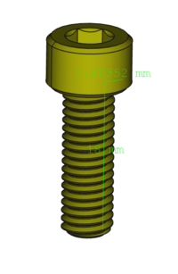
Figuring out how to create the M6x18-Screw File:M6x18.fcstd
Wed Apr 12, 2017
I followed the D3D Assembly Animation Script for the Axis Idler Side and this is the result: File:Idler side 01.fcstd

