D3D v19.04
![]() Hint: This is not the latest version of the 3D Printer. See D3D v19.06 for the current version.
Hint: This is not the latest version of the 3D Printer. See D3D v19.06 for the current version.
Contents
Scrumy
Overview
- Builds on the D3D v19.02 3D printer.
Features
- Eco edition - insulated heatbed for 30%-60% lower energy consumption while printing with heated bed
- Upgraded to 24V control system
- Silent stepper drivers - uses TMC2208 in legacy mode instead of A4988
- 500W heatbed for 1 minute bed heatup time
- Added built-in GFCI electrical safety breaker as a standard feature
- Still uses the Titan Aero extruder with 3 mm nozzle
- Auto bed leveling with babystepping correction
Future Work
- Dual extruders borrowed from LulzBot TAZ Pro
- Supervolcano Nozzle add-on
- Rubber optimized extruder - see Rubber Extruder
Working Doc
Build Checklist
- Prior to first turn-on, verify that all axes move smoothly through their full range of motion, without interference with structure, bolts, wiring, or endstops.
- Before first turn-on, make sure you removed the D1 diode for powering the Arduino. This is the only thing that can fry your arduino.
- Upload Marlin v19.04 if not uploaded yet. Do you have Marlin v19.04? Make sure it's not v19.02 or earlier
- Power up arduino on USB only
- Power up arduino via 12V connection after verifying that USB connection works.
- Verify that the capacitors under the stepper drivers are rated for 35V.
- Check 24V and 12V coming from power supply/ Verify that the top of the power plug (closest to screw-down terminals) is 12V, and 24V for the bottom section.
- Go to Cura, load an object, and in control screen command line - use M119 to check endstop status to make sure that they are not triggered. Check 3 endstops for proper triggering. They should be OPEN in the Cura window when not engaged, and TRIGGERED when engaged. Note the Code Change Log for changes when simpler endstops are used
- Check for motion of X, Y, and Z using Cura.
- Check heater and heatbed using Cura.
- Once that is all good, adjust endstop height so bottom of blue probe is at the flat part of the nozzle above the conical part of the nozzle
- You're ready for first print.
CAD
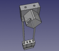
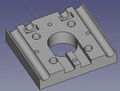
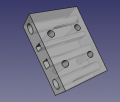
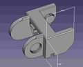
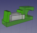
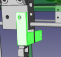
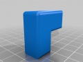
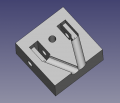
![]() Hint: Tasks: (1) Updating Y axis holding bracket including 3D printed Corner Fit. (2) New insulated bed. (3) 3D Printed Control Panel. (4) Offset cable chain start piece.
Hint: Tasks: (1) Updating Y axis holding bracket including 3D printed Corner Fit. (2) New insulated bed. (3) 3D Printed Control Panel. (4) Offset cable chain start piece. 
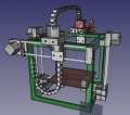
Printer
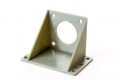
Design Rationale:
- 0.26 diameter hole through frame (6.6 mm) and through Y mount to frame


D3D v19.02 Final Assembly - size:nullkb - FreeCAD -File:D3Dfinalassemblyv1902.fcstd
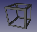
12" Frame - size:nullkb - FreeCAD -File:Frame1902.fcstd
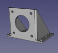
Bracket for bonding frame together without welding. - FreeCAD -File:Framebracket.fcstd. STL - File:Framebracket.stl
Z1 axis - size:nullkb - FreeCAD -File:Z1D3Dv1902.fcstd
 [10] Motor Side of Axis - 221k - FreeCAD -File:Universal axis motor side.fcstd. STL - File:Universal axis motor side.stl
Universal axis carriage: File:Universal axis carriage side.fcstd. STL - File:Universal axis carriage side.stl
Half carriage: File:Axis half carriage.fcstd. STL - File:Axis half carriage.stl
 [10] Short Idler Side - 75k - FreeCAD - File:Universal Axis Idler Side short version.fcstd. STL - File:Universal Axis Idler Side short version.stl.
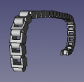 X cable chain - FreeCAD - File:X cable chain.fcstd.
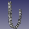 Y cable chain - FreeCAD - File:Y cable chain.fcstd.
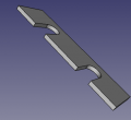
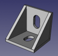 Y Cable Chain Mounting Bracket. - FreeCAD - File:Cable chain bracket.fcstd. STL - File:Cablechainbracket.stl.
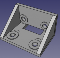
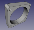
XY Bracket - FreeCAD - File:Xy bracket.fcstd. STL - File:Xy bracket.stl.
 Cable Chain Main Link. Note that FreeCAD file is simplified. No FreeCAD source exists outside of STL.. File:Link.fcstd. STL - File:Link.stl
 Beginning Cable Piece - File:D3dcablechain beginning.stl.
- End Cable Piece - File:D3dcablechain end.fcstd. File:D3dcablechain end.stl.
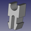
 Offset Cable Chain Piece - File:Offsetcablechain.fcstd. File:Offsetcablechain.stl.
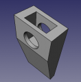
Endstop holder. - File:Endstopholder2.fcstd. File:Endstopholder2.stl. See Open Source Endstop Holder
Generic limit switch. - File:Limitswitch.fcstd. Source: [1]
Endstop holder assembly. - File:Endstop assy.fcstd.
Second cablechain holder. - File:Secondcableholder.fcstd. File:Secondcableholder.stl.
Spacer. - File:Spacer.fcstd. File:Spacer.stl. 8 for 1 machine - File:8spacers.stl.
E3D Titan Bracket. - File:E3dtitanbracket.fcstd. File:E3dtitanbracket.stl.Source - [2]
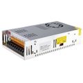
LFX_24V Power Supply - size:nullkb - FreeCAD -File:LFX 24V Power Supply.fcstd
 Spool Holder. File: File:Spoolholder.stl Link for more types of these joints - [3]


Itemized:
- Frame
- Carriage
- Motor piece
- Idler piece
- Half-carriage with regular bearings
- Rods
- Extruder
- Endstop
- Heated Bed
- Cable chain start, simplified
- Cable chain end, simplified
- Cable chain link, simplified
- 18 mm bolt
- 30 mm bolt
- Angle for holding X to Y axis
- Controller - power supply - borrow from Lyman Filament Extruder
- Controller - Arduino
- Controller - RAMPS
- Controller - LCD screen - reverse engineer from drawing?
- Controller - MOSFET
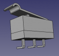
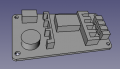
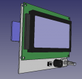
Control Panel
See more at 3D Printer Control Panel


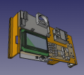
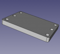
Control Panel - FreeCAD -File:Controlpanel v1904.fcstd. Bent panel STL - File:Bentpanel v1904.stl
D3D v19.04 Power Supply - FreeCAD -File:Powersupply v1904.fcstd
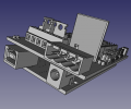
RAMPS 1.4 - FreeCAD -File:RAMPS14 v1904.fcstd. Full detailed file - 4MB - [4]
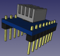
Stepper driver - FreeCAD -File:Stepperdriver v1904.fcstd. File for detailed LCD controller and endstop can be found at [5]
Solid state relay - FreeCAD -File:Ssr v1904.fcstd. Source: [6]. See Fotek SSR. Dimensions verified with Amazon source.
Reprap Discount Smart Controller - FreeCAD -File:Smartcontroller v1904.fcstd. Source: [7].
Ground Fault Connection Interrupt (GFCI) outlet - FreeCAD -File:Gfci v1904.fcstd. CAD source at McMaster Carr: [8]. May not represent actual GFCI.
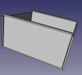
Wire box cover. - FreeCAD -File:Wireboxcover v1904.fcstd.
Power cord wire clamp - FreeCAD -File:Heatbed wirelock.fcstd.
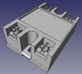
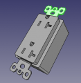
Inner part of D3D Electric Plug - FreeCAD File:D3DPlugInner.fcstd. STL - File:D3DPlugInner.stl
Outer cover of D3D Electric Plug - FreeCAD File:D3DPlugCover.fcstd. STL file is scaled to 105% already - File:D3DPlugCover.stl
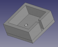
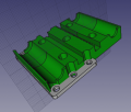
Heatbed


D3D v19.02 Final Assembly - FreeCAD -File:D3Dfinalassemblyv1902.fcstd
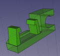
Heatbed snap-buckle for mounting bed. - size:nullkb - FreeCAD -File:Heatbed snapbuckle1904.fcstd
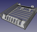
heatbed_body1904 - FreeCAD - File:Heatbed body1904.fcstd. STL - File:Heatbed body1904.stl. 93% - 7.44" - File:Heatbed93.stl
Wire lock - FreeCAD - File:Heatbed wirelock.fcstd.
Frame

D3D v19.02 Final Assembly - size:nullkb - FreeCAD -File:D3Dfinalassemblyv1902.fcstd
12" Frame - size:nullkb - FreeCAD -File:Frame1902.fcstd
Frame spacer - size:nullkb - FreeCAD -File:Framespacer v1904.fcstd
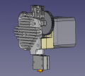
Extruder


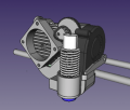
OSE Extruder v19.02 - File:Oseextruder1902.fcstd. Volcano version, tighter fit on carriage, auto Y alignment.
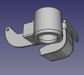
OSE Extruder nozzle assemby. Holds fan and sensor. File:Nozzleassembly.fcstd. STL - File:Nozzleassembly.stl
Stock Titan Aero mount bracket. See [9]. Bracket - [10] - STEP + STL. Check out drawings from E3D - [11]. STEP of Bracket - File:Bracket.fcstd
Titan Aero with motor - [12]
Titan Aero mount top plate. File:Brackettop.fcstd. STL - File:Brackettop.stl
Simplified carriage: File:Universal axis carriage side.fcstd. (From D3D Part Library)
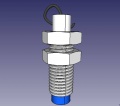
8 mm sensor. Download - File:8mmsensor.fcstd
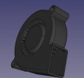
File:5015blower.fcstd 5015 Blower
File:40x10fan.fcstd 40x10mm fan
File:Extruderspacer.fcstd Extruder spacer. File:Extruderspacer.stl


BOM
Parts
- SSR -
- GFCI - [13]
- Power Supply - [14]
- Nichrome wire 26 ga 12' - [15]
- Fiberglass sleeve - [16]
- Crimps
- Spade terminal brass -
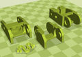
3D Printed Files and Production Engineering
- Printer Profile - File:V1904 04 Production.ini using D3D v19.02 or D3D_v18.12
- Number in brackets is number of pieces needed per machine
- [8] Frame Corners - File:Framebracket.fcstd. 1 - File:Framebracket.stl. 8 - File:8corners.stl - 4:51 hr + 73 g PLA.
- [1] Control Panel - File:Controlpanel v1904.fcstd. 1 - File:Bentpanel v1904.stl - 7:28 hr and 111 g PLA.
- [4] Short carriage - File:Axis half carriage.fcstd. 1 - File:Axis half carriage.stl - 45 min 10 g PLA. 4 - File:4 Axis half carriage.stl - 2:41 hr, 40 g PLA
- [6] Carriage - File:Universal axis carriage side.fcstd. 1 - File:Universal axis carriage side.stl - 1:14 hr, 18 g PLA. 6 - 6 Carriages for printing - 7:26 hr + 108 g PLA
- [1] Offset Cable Chain - File:Offsetcablechain.fcstd. 1 - File:Offsetcablechain.stl. 18 min + 4 g PLA.
- [1] Sensor Holder - File:Nozzleassembly.fcstd. 1 - File:Nozzleassembly.stl - 1:01 hr and 14 g PLA
- [1] Extruder Mount Integrated Into Carriage - File:Brackettop.fcstd. 1 - File:Brackettop.stl. 1:12 hr + 18 g PLA.
- [1] Plug Top - File:D3DPlugCover.fcstd. 1 - File:D3DPlugCover.stl. 18 min + 5 g PLA.
- [1] Plug Bottom - File:D3DPlugInner.fcstd. 1 - File:D3DPlugInner.stl - 13 min + 3 g PLA.
- [2] Endstops - File:Endstopholder2.fcstd. 1 - File:Endstopholder2.stl - 7 min 2 g PLA. 2 - File:2 endstops.stl - 13 min 4 g PLA.
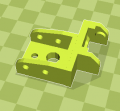
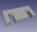
- [2] XY bracket with hole - File:Xy bracket.fcstd. 1 - File:Xy bracket.stl - 2nd in history - 40 min 10 g. 2 brackets with hole - File:2 xy bracket.stl
- [2] Y Axis Mount bracket - pair of them - File:Y mount bracket.stl. For source, see above line.
More
- [10] Idler Piece - File:Universal Axis Idler Side short version.fcstd. 1 - File:Universal Axis Idler Side short version.stl. 10 - File:10 idler pieces.stl
- [10] Motor Piece - File:Universal axis motor side.fcstd. 1 - File:Universal axis motor side.stl. 10 - File:10 motor pieces.stl
- [50] Cable chain - File:Link.fcstd. 1 - File:Link.stl. 42 - File:42 cablechain.stl
- [2] Cable chain end - File:D3dcablechain end.fcstd. 1 - File:D3dcablechain end.stl. 2 - File:2 cablechain end.stl
- [1] Control Panel Wire Cover - File:Wireboxcover v1904.fcstd. 1 - File:Wireboxcover v1904.stl
- [1] Extruder Bracket - File:E3dtitanbracket.fcstd. 1 - File:E3dtitanbracket.stl. 10 - [[]]
[2] Y-Axis Bracket - [[]]. 1 - [[]]. 10 - [[]]- [10] Belt Peg - File:Peg 8mm rods.fcstd. 1 - File:Peg 8mm rods.stl. 10 - File:10pegs.stl - 6 large, 4 small.
- Spool holder
Fabrication
- D3D v19.02 used for gross parts (panel, heatbed). Using File:D3D v19.02 Working Profile.ini - slight mod of original with thinner top and bottom.
- D3D v18.12 used for fine parts. Using File:D3D 14inchframe Titan Aero Omni Shroud 04 175.ini same as before. Later parts used 2.85mm PLA filament.
Frame Build
Axes
Control Panel Build
Plug
Heatbed
Pictures
Google Folder - [17]
Code
- Marlin - File:Marlin v1904.zip.
- Change log:
- Endstop_reversing was reversed on X and Y compared to pre v19.02 versions, where we now use default after going to plain endstop, and not the endstop breakout board. Optimizing bed coordinates and bed probing in Marlin. Marlin v19.04 can be used with v19.02 and should be the 8" bed standard from now on.
- Mintemp reduced to 1C from 5C - to allow near freezing performance. Kept above 0, as 0 means disconnected. Thus, thermistor lockout is still present
- Changed 408 to 425 steps per mm for Titan Aero - #define DEFAULT_AXIS_STEPS_PER_UNIT { 80, 80, 80, 425 }
- Change probe location from 20 to -20 - #define X_PROBE_OFFSET_FROM_EXTRUDER -20
- Changed X and Y bed limits to 8" - #define Y_MAX_POS 204 //changed from 175
- define LEFT_PROBE_BED_POSITION 40 // changed from 20
- define BACK_PROBE_BED_POSITION 160 //changed from 150. All together ~40 mm off each edge
- Config file - 0.8 mm nozzle - File:D3d profile 1904.ini