D3D v19.06/fr
Explosion
3D Explosion View - index page - https://mi_shell.gitlab.io/models_online
D3D explosion view model - https://mi_shell.gitlab.io/models_online/ose_webgl/d3d_explosion.html
Build
Build Outcomes
- 178C heat bed has been validated and perfected. Improvements: shortening insulated nichrome length of heating coil from 12' to 6' to facilitate threading of nichrome through insulation.
Build Notes
Collaboration Areas
- Universal Frame Builder - parametric FreeCAD spreadsheet for designing different frame variations for the 3D Printer Construction Set, with export of DXF files. Exporting nested DXF files.
- Universal Axis Builder - Universal Axis Generator at the 8 mm size for variations of bolt length, belt lengths, and rod lengths; allows multiple carriages. Exports to simplified version of the axis for collaborative design.
- Universal Heatbed Builder - spreadsheet bed generator for varying size, heating coils, and bed support mounting. Multiple coils for energy saving can be applied.
- Universal Controller Builder - Universal Controller of different sizes for different size frames, and for varying the number of components such as relays, analog controllers, and other components of choice.
- 3D Printer Product Strategy
Critical Path
- This is Distributive Enterprise Release Candidate.
- Rationale - go to 120V heat bed to reduce power supply size.
- Don't include TMC2130 initially as that will take time to optimize, even though it gets rid of the end stops. Use TMC2208 now.
- Include clean wiring
- Include 3D printed corners
Goals:
- Building new heated bed allows for a high performance printer
- With 3D Printed control panel, electronics become simpler for builds
- Silent operation is a good upgrade
Collaboration
CAD
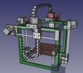
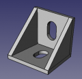
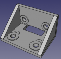
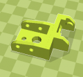
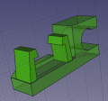
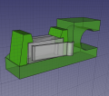
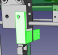
![]() Hint: Tasks: (1) Updating Y axis holding bracket including 3D printed Corner Fit. (2) New insulated bed. (3) 3D Printed Control Panel. (4) Offset cable chain start piece.
Hint: Tasks: (1) Updating Y axis holding bracket including 3D printed Corner Fit. (2) New insulated bed. (3) 3D Printed Control Panel. (4) Offset cable chain start piece. 
Printer
Design Rationale:
- 0.26 diameter hole through frame (6.6 mm) and through Y mount to frame


D3D v19.02 Final Assembly - size:nullkb - FreeCAD -File:D3Dfinalassemblyv1902.fcstd
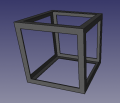
12" Frame - FreeCAD -File:Frame1902.fcstd
Bracket for bonding frame together without welding. - FreeCAD -File:Framebracket.fcstd. STL - File:Framebracket.stl
Z1 axis - FreeCAD -File:Z1D3Dv1902.fcstd
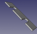
![[10] Motor Side of Axis - 221k - FreeCAD -File:Universal axis motor side.fcstd. STL - File:Universal axis motor side.stl](/images/thumb/4/45/Motorside.jpg/120px-Motorside.jpg)
 [10] Motor Side of Axis - 221k - FreeCAD -File:Universal axis motor side.fcstd. STL - File:Universal axis motor side.stl
Universal axis carriage: File:Universal axis carriage side.fcstd. STL - File:Universal axis carriage side.stl
Half carriage: File:Axis half carriage.fcstd. STL - File:Axis half carriage.stl
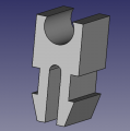
![[10] Short Idler Side - 75k - FreeCAD - File:Universal Axis Idler Side short version.fcstd. STL - File:Universal Axis Idler Side short version.stl.](/images/thumb/a/ae/Idlershort.jpg/120px-Idlershort.jpg) [10] Short Idler Side - 75k - FreeCAD - File:Universal Axis Idler Side short version.fcstd. STL - File:Universal Axis Idler Side short version.stl.
[10] Short Idler Side - 75k - FreeCAD - File:Universal Axis Idler Side short version.fcstd. STL - File:Universal Axis Idler Side short version.stl.
![[10] Belt Holding Peg - FreeCAD original size - File:Peg 8mm rods.fcstd. STL at 85% size, works well - File:Peg 8mm rods.stl](/images/thumb/a/a5/Peg85.jpg/120px-Peg85.jpg) [10] Belt Holding Peg - FreeCAD original size - File:Peg 8mm rods.fcstd. STL at 85% size, works well - File:Peg 8mm rods.stl
[10] Belt Holding Peg - FreeCAD original size - File:Peg 8mm rods.fcstd. STL at 85% size, works well - File:Peg 8mm rods.stl
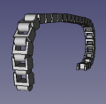 X cable chain - FreeCAD - File:X cable chain.fcstd.
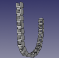 Y cable chain - FreeCAD - File:Y cable chain.fcstd.
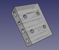
 Y Cable Chain Mounting Bracket. - FreeCAD - File:Cable chain bracket.fcstd. STL - File:Cablechainbracket.stl.
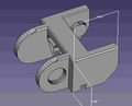
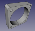
XY Bracket - FreeCAD - File:Xy bracket.fcstd. STL - File:Xy bracket.stl.
 Cable Chain Main Link. Note that FreeCAD file is simplified. No FreeCAD source exists outside of STL.. File:Link.fcstd. STL - File:Link.stl
 Beginning Cable Piece - File:D3dcablechain beginning.stl.
- End Cable Piece - File:D3dcablechain end.fcstd. File:D3dcablechain end.stl.
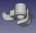
 Offset Cable Chain Piece - File:Offsetcablechain.fcstd. File:Offsetcablechain.stl.
Endstop holder. - File:Endstopholder2.fcstd. File:Endstopholder2.stl. See Open Source Endstop Holder
![Generic limit switch. - File:Limitswitch.fcstd. Source: [1]](/images/thumb/2/2e/Limitswitch.png/120px-Limitswitch.png)
Generic limit switch. - File:Limitswitch.fcstd. Source: [1]
Endstop holder assembly. - File:Endstop assy.fcstd.
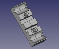
Second cablechain holder. - File:Secondcableholder.fcstd. File:Secondcableholder.stl.
Spacer. - File:Spacer.fcstd. File:Spacer.stl. 8 for 1 machine - File:8spacers.stl.
![E3D Titan Bracket. - File:E3dtitanbracket.fcstd. File:E3dtitanbracket.stl.Source - [2]](/images/thumb/7/79/E3dtitanbracket.png/120px-E3dtitanbracket.png)
E3D Titan Bracket. - File:E3dtitanbracket.fcstd. File:E3dtitanbracket.stl.Source - [2]
LFX_24V Power Supply - size:nullkb - FreeCAD -File:LFX 24V Power Supply.fcstd
![Spool Holder. File: File:Spoolholder.stl Link for more types of these joints - [3]](/images/thumb/d/d6/Spoolholderjoint.jpg/120px-Spoolholderjoint.jpg) Spool Holder. File: File:Spoolholder.stl Link for more types of these joints - [3]
Spool Holder. File: File:Spoolholder.stl Link for more types of these joints - [3]
![[10] Motor Side of Axis - 221k - FreeCAD -File:Universal axis motor side.fcstd. STL - File:Universal axis motor side.stl](/wiki/File:Motorside.jpg)

![[10] Short Idler Side - 75k - FreeCAD - File:Universal Axis Idler Side short version.fcstd. STL - File:Universal Axis Idler Side short version.stl.](/wiki/File:Idlershort.jpg)


![Spool Holder. File: File:Spoolholder.stl Link for more types of these joints - [3]](/wiki/File:Spoolholderjoint.jpg)
Itemized:
- Frame
- Carriage
- Motor piece
- Idler piece
- Half-carriage with regular bearings
- Rods
- Extruder
- Endstop
- Heated Bed
- Cable chain start, simplified
- Cable chain end, simplified
- Cable chain link, simplified
- 18 mm bolt
- 30 mm bolt
- Angle for holding X to Y axis
- Controller - power supply - borrow from Lyman Filament Extruder
- Controller - Arduino
- Controller - RAMPS
- Controller - LCD screen - reverse engineer from drawing?
- Controller - MOSFET
Control Panel
See more at 3D Printer Control Panel


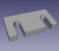
Control Panel - FreeCAD -File:Controlpanel v1904.fcstd. Bent panel STL - File:Bentpanel v1904.stl
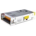
D3D v19.04 Power Supply - FreeCAD -File:Powersupply v1904.fcstd
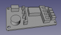
![RAMPS 1.4 - FreeCAD -File:RAMPS14 v1904.fcstd. Full detailed file - 4MB - [4]](/images/thumb/a/a5/RAMPS14_v1904.png/120px-RAMPS14_v1904.png)
RAMPS 1.4 - FreeCAD -File:RAMPS14 v1904.fcstd. Full detailed file - 4MB - [4]
![Stepper driver - FreeCAD -File:Stepperdriver v1904.fcstd. File for detailed LCD controller and endstop can be found at [5]](/images/thumb/a/a8/Stepperdriver_v1904.png/120px-Stepperdriver_v1904.png)
Stepper driver - FreeCAD -File:Stepperdriver v1904.fcstd. File for detailed LCD controller and endstop can be found at [5]
![Solid state relay - FreeCAD -File:Ssr v1904.fcstd. Source: [6]. See Fotek SSR. Dimensions verified with Amazon source.](/images/thumb/b/ba/Ssr_v1904.png/120px-Ssr_v1904.png)
Solid state relay - FreeCAD -File:Ssr v1904.fcstd. Source: [6]. See Fotek SSR. Dimensions verified with Amazon source.
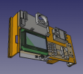
![Reprap Discount Smart Controller - FreeCAD -File:Smartcontroller v1904.fcstd. Source: [7].](/images/thumb/f/fe/Smartcontroller_v1904.png/120px-Smartcontroller_v1904.png)
Reprap Discount Smart Controller - FreeCAD -File:Smartcontroller v1904.fcstd. Source: [7].
![Ground Fault Connection Interrupt (GFCI) outlet - FreeCAD -File:Gfci v1904.fcstd. CAD source at McMaster Carr: [8]. May not represent actual GFCI.](/images/thumb/5/50/Gfci_v1904.png/117px-Gfci_v1904.png)
Ground Fault Connection Interrupt (GFCI) outlet - FreeCAD -File:Gfci v1904.fcstd. CAD source at McMaster Carr: [8]. May not represent actual GFCI.
Wire box cover. - FreeCAD -File:Wireboxcover v1904.fcstd.
Power cord wire clamp - FreeCAD -File:Heatbed wirelock.fcstd.
Inner part of D3D Electric Plug - FreeCAD File:D3DPlugInner.fcstd. STL - File:D3DPlugInner.stl
Outer cover of D3D Electric Plug - FreeCAD File:D3DPlugCover.fcstd. STL file is scaled to 105% already - File:D3DPlugCover.stl
Heatbed


D3D v19.02 Final Assembly - FreeCAD -File:D3Dfinalassemblyv1902.fcstd
Heatbed snap-buckle for mounting bed. - size:nullkb - FreeCAD -File:Heatbed snapbuckle1904.fcstd
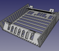
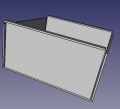
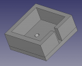
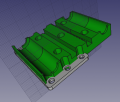
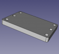
heatbed_body1904 - FreeCAD - File:Heatbed body1904.fcstd. STL - File:Heatbed body1904.stl. 93% - 7.44" - File:Heatbed93.stl
Wire lock - FreeCAD - File:Heatbed wirelock.fcstd.
Frame

D3D v19.02 Final Assembly - size:nullkb - FreeCAD -File:D3Dfinalassemblyv1902.fcstd
12" Frame - size:nullkb - FreeCAD -File:Frame1902.fcstd
Frame spacer - size:nullkb - FreeCAD -File:Framespacer v1904.fcstd
Extruder


OSE Extruder v19.02 - File:Oseextruder1902.fcstd. Volcano version, tighter fit on carriage, auto Y alignment.
OSE Extruder nozzle assemby. Holds fan and sensor. File:Nozzleassembly.fcstd. STL - File:Nozzleassembly.stl
![Stock Titan Aero mount bracket. See [9]. Bracket - [10] - STEP + STL. Check out drawings from E3D - [11]. STEP of Bracket - File:Bracket.fcstd](/images/thumb/5/51/Titanstockholder.jpg/120px-Titanstockholder.jpg)
Stock Titan Aero mount bracket. See [9]. Bracket - [10] - STEP + STL. Check out drawings from E3D - [11]. STEP of Bracket - File:Bracket.fcstd
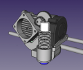
![Titan Aero with motor - [12]](/images/thumb/7/78/Titanwithmotor.png/120px-Titanwithmotor.png)
Titan Aero with motor - [12]
Titan Aero mount top plate. File:Brackettop.fcstd. STL - File:Brackettop.stl
Simplified carriage: File:Universal axis carriage side.fcstd. (From D3D Part Library)
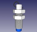
8 mm sensor. Download - File:8mmsensor.fcstd
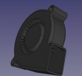
File:5015blower.fcstd 5015 Blower
File:40x10fan.fcstd 40x10mm fan
File:Extruderspacer.fcstd Extruder spacer. File:Extruderspacer.stl

![Stock Titan Aero mount bracket. See [9]. Bracket - [10] - STEP + STL. Check out drawings from E3D - [11]. STEP of Bracket - File:Bracket.fcstd](/wiki/File:Titanstockholder.jpg)
![Titan Aero with motor - [12]](/wiki/File:Titanwithmotor.png)


Build Instructions
Frame Build
Control Panel Build
Plug
Heatbed
Current heatbed uses 16 ga steel plate, and the print surface is 1/8" steel plate with PEI surface on top cut to size, attached with 3M double-sided adhesive. The max continuous temperature of this heatbed is 178C, and it heats up faster than the extruder. It overshoots temperature when cycling to set point, which still works but can be tuned. Standard print bed setting was 80C. When attaching the thermistor, insulate it from the nichrome heater so it reflects more the temperature of the print surface, not the heater element. More heatbed build pictures in Google Folder - [13]
More pictures from STEAM Camp 2019 -
BOM
Printed Parts
v19.06 BOM Details
Parts
- SSR -
- GFCI - [14]
- Power Supply - [15]
- Nichrome wire 26 ga 12' - [16]
- Fiberglass sleeve - [17]
- Crimps
- Spade terminal brass -
3D Printed Files and Production Engineering
- Printer Profile - File:V1904 04 Production.ini using D3D v19.02 or D3D_v18.12
- Number in brackets is number of pieces needed per machine
- [8] Frame Corners - File:Framebracket.fcstd. 1 - File:Framebracket.stl. 8 - File:8corners.stl - 4:51 hr + 73 g PLA.
- [1] Control Panel - File:Controlpanel v1904.fcstd. 1 - File:Bentpanel v1904.stl - 7:28 hr and 111 g PLA.
- [4] Short carriage - File:Axis half carriage.fcstd. 1 - File:Axis half carriage.stl - 45 min 10 g PLA. 4 - File:4 Axis half carriage.stl - 2:41 hr, 40 g PLA
- [6] Carriage - File:Universal axis carriage side.fcstd. 1 - File:Universal axis carriage side.stl - 1:14 hr, 18 g PLA. 6 - 6 Carriages for printing - 7:26 hr + 108 g PLA
- [1] Offset Cable Chain - File:Offsetcablechain.fcstd. 1 - File:Offsetcablechain.stl. 18 min + 4 g PLA.
- [1] Sensor Holder - File:Nozzleassembly.fcstd. 1 - File:Nozzleassembly.stl - 1:01 hr and 14 g PLA
- [1] Extruder Mount Integrated Into Carriage - File:Brackettop.fcstd. 1 - File:Brackettop.stl. 1:12 hr + 18 g PLA.
- [1] Plug Top - File:D3DPlugCover.fcstd. 1 - File:D3DPlugCover.stl. 18 min + 5 g PLA.
- [1] Plug Bottom - File:D3DPlugInner.fcstd. 1 - File:D3DPlugInner.stl - 13 min + 3 g PLA.
- [2] Endstops - File:Endstopholder2.fcstd. 1 - File:Endstopholder2.stl - 7 min 2 g PLA. 2 - File:2 endstops.stl - 13 min 4 g PLA.
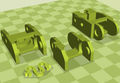
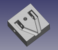
- [2] XY bracket with hole - File:Xy bracket.fcstd. 1 - File:Xy bracket.stl - 2nd in history - 40 min 10 g. 2 brackets with hole - File:2 xy bracket.stl
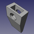
- [2] Y Axis Mount bracket - pair of them - File:Y mount bracket.stl. For source, see above line.
More
- [10] Idler Piece - File:Universal Axis Idler Side short version.fcstd. 1 - File:Universal Axis Idler Side short version.stl. 10 - File:10 idler pieces.stl
- [10] Motor Piece - File:Universal axis motor side.fcstd. 1 - File:Universal axis motor side.stl. 10 - File:10 motor pieces.stl
- [50] Cable chain - File:Link.fcstd. 1 - File:Link.stl. 42 - File:42 cablechain.stl
- [2] Cable chain end - File:D3dcablechain end.fcstd. 1 - File:D3dcablechain end.stl. 2 - File:2 cablechain end.stl
- [1] Control Panel Wire Cover - File:Wireboxcover v1904.fcstd. 1 - File:Wireboxcover v1904.stl
- [1] Extruder Bracket - File:E3dtitanbracket.fcstd. 1 - File:E3dtitanbracket.stl. 10 - [[]]
[2] Y-Axis Bracket - [[]]. 1 - [[]]. 10 - [[]]- [10] Belt Peg - File:Peg 8mm rods.fcstd. 1 - File:Peg 8mm rods.stl. 10 - File:10pegs.stl - 6 large, 4 small.
- Spool holder
Production Engineering
Wiring
See also Universal Controller
Testing MTA-100 Connectors
Shopping list from Digikey:

Heated Enclosure
Heated Chamber
Prior art - see Heated Build Chamber Patents
Quality Control, Troubleshooting, and Repair
So now you have built your machine and controller. Now here is how to make it work as expected, going through an exhaustive list of potential issues, prior to cleaning up all the wiring.
Quality Control
Suggested Bulk Procedure
- Test that power lights on all power supplies
- For faulty power supply, connect to the back terminals?
- Wires for the power supply to RAMPS - one line for 12V, 2 lines for 24V. Prevents wiring mistakes.
- Use ferrules on wires, and only one wire per clamb-down terminal. If multiple, join them elsewhere.
- Clear wiring labels
- Extruder fan - 1 line on red/black wire
- Print cooling fan - 2 lines on red/black wire - or use different color wire
- Extruder heater block- should be high t wire, different than others.
Troubleshooting Guide
Covers:
- Power supply power cable issues
Cleaning Up the Wiring
The final wire routing should look like this on the control panel:
- All wires tight and out of the way
- Any wire that is too long is pulled behind the Control panel or near the cable chain and zip tied neatly to other wires or fixing points.
- All wiring is kept accessible for repairs and upgrades
- A shield is placed in front of the power supply to prevent any shocks.
- Wires from stepper motors are hidden along the corners of the frame
- Stepper motor wires are oriented so that the closest path to the control panel results.
Code
Printer Profile in Lulzbot Cura for OSE D3D v19.06
- File:V1906-4-08.ini - printer 4. 0.8 mm nozzle.
Bugs
- Windows version software toolchain needs full documentation
- OSE Linux needs updating with latest Cura and FreeCAD
- OSE Linux instructional for making ISO needs updating
- Discourse needs to be set up for Development discussion
- Askbot needs to be set up for customer support (and development)
Links
- D3D v19.04 - full CAD library for the printer and firmware
- D3D v19.11