D3D Pro: Difference between revisions
| Line 20: | Line 20: | ||
|- | |- | ||
! scope=row | 1 | ! scope=row | 1 | ||
| [[Requirements + Value Proposition]] || [[D3D Pro | | [[Requirements + Value Proposition]] || [[D3D Pro Requirements + Value Proposition]] || {{{1}}} | ||
|- | |- | ||
! scope=row | 2 | ! scope=row | 2 | ||
| [[Industry_Standards]] || [[D3D Pro | | [[Industry_Standards]] || [[D3D Pro Industry Standards]] || {{{2}}} | ||
|- | |- | ||
! scope=row | 3 | ! scope=row | 3 | ||
| [[Conceptual Design]] || [[D3D Pro | | [[Conceptual Design]] || [[D3D Pro Conceptual Design]] || {{{3}}} | ||
|- | |- | ||
! scope=row | 4 | ! scope=row | 4 | ||
| [[Module Breakdown]] || [[D3D Pro | | [[Module Breakdown]] || [[D3D Pro Module Breakdown]] || {{{4}}} | ||
|- | |- | ||
! scope=row | 5 | ! scope=row | 5 | ||
| [[3D CAD]] || [[D3D Pro | | [[3D CAD]] || [[D3D Pro 3D CAD]] || {{{5}}} | ||
|- | |- | ||
! scope=row | 6 | ! scope=row | 6 | ||
| [[Calculations]] || [[D3D Pro | | [[Calculations]] || [[D3D Pro Calculations]] || {{{6}}} | ||
|- | |- | ||
! scope=row | 7 | ! scope=row | 7 | ||
| [[Electronics Design]] || [[D3D Pro | | [[Electronics Design]] || [[D3D Pro Electronics Design]] || {{{7}}} | ||
|- | |- | ||
! scope=row | 8 | ! scope=row | 8 | ||
| [[Wiring and Plumbing]] || [[D3D Pro | | [[Wiring and Plumbing]] || [[D3D Pro Wiring and Plumbing]] || {{{8}}} | ||
|- | |- | ||
! scope=row | 9 | ! scope=row | 9 | ||
| [[Software]] || [[D3D Pro | | [[Software]] || [[D3D Pro Software]] || {{{9}}} | ||
|- | |- | ||
| Line 60: | Line 60: | ||
|- | |- | ||
! scope=row | 10 | ! scope=row | 10 | ||
| [[BOM]] || [[D3D Pro | | [[BOM]] || [[D3D Pro BOM]] || {{{10}}} | ||
|- | |- | ||
! scope=row | 11 | ! scope=row | 11 | ||
| [[vBOM]] || [[D3D Pro | | [[vBOM]] || [[D3D Pro vBOM]] || {{{11}}} | ||
|- | |- | ||
! scope=row | 12 | ! scope=row | 12 | ||
| [[CAM Files]] || [[D3D Pro | | [[CAM Files]] || [[D3D Pro CAM Files]] || {{{12}}} | ||
|- | |- | ||
! scope=row | 13 | ! scope=row | 13 | ||
| [[Cut List]] || [[D3D Pro | | [[Cut List]] || [[D3D Pro Cut List]] || {{{13}}} | ||
|- | |- | ||
| Line 80: | Line 80: | ||
|- | |- | ||
! scope=row | 14 | ! scope=row | 14 | ||
| [[Build Instructions]] || [[D3D Pro | | [[Build Instructions]] || [[D3D Pro Build Instructions]] || {{{14}}} | ||
|- | |- | ||
! scope=row | 15 | ! scope=row | 15 | ||
| [[Fabrication Drawings]] || [[D3D Pro | | [[Fabrication Drawings]] || [[D3D Pro Fabrication Drawings]] || {{{15}}} | ||
|- | |- | ||
! scope=row | 16 | ! scope=row | 16 | ||
| [[Exploded Part Diagram]] || [[D3D Pro | | [[Exploded Part Diagram]] || [[D3D Pro Exploded Part Diagram]] || {{{16}}} | ||
|- | |- | ||
! scope=row | 17 | ! scope=row | 17 | ||
| [[Production Engineering]] || [[D3D Pro | | [[Production Engineering]] || [[D3D Pro Production Engineering]] || {{{17}}} | ||
|- | |- | ||
| Line 100: | Line 100: | ||
|- | |- | ||
! scope=row | 18 | ! scope=row | 18 | ||
| [[Build Pictures and Video]] || [[D3D Pro | | [[Build Pictures and Video]] || [[D3D Pro Build Pictures and Video]] || {{{18}}} | ||
|- | |- | ||
! scope=row | 19 | ! scope=row | 19 | ||
| [[Data Collection]] || [[D3D Pro | | [[Data Collection]] || [[D3D Pro Data Collection]] || {{{19}}} | ||
|- | |- | ||
! scope=row | 20 | ! scope=row | 20 | ||
| [[Future Work]] || [[D3D Pro | | [[Future Work]] || [[D3D Pro Future Work]] || {{{20}}} | ||
|} | |} | ||
Revision as of 04:11, 23 April 2020
Intro

You can get a ready-to-build kit at https://www.opensourceecology.org/d3d-pro/
Development
CAD


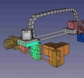
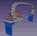
Updated gantry for D3D Pro. - FreeCAD -File:D3d1911.fcstd
16" Frame - FreeCAD -File:Frame16.fcstd
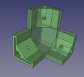
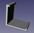
Angle Connector. - FreeCAD with McMaster 6 mm nut -File:Angleconnector.fcstd. Finished STL - File:Anglecorner.stl
Angle Connector with axis mount, left side. - FreeCAD - File:Leftcorner.fcstd. Finished STL - File:Leftcorner.stl
Angle Connector with axis mount, right side. - FreeCAD - File:Rightcorner.fcstd. Finished STL - File:Rightcorner.stl
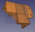
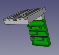
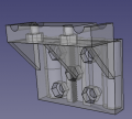
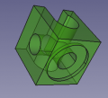
![[10] Motor Side of Axis - 221k - FreeCAD -File:Universal axis motor side.fcstd. STL - File:Universal axis motor side.stl](/images/thumb/4/45/Motorside.jpg/120px-Motorside.jpg)
 [10] Motor Side of Axis - 221k - FreeCAD -File:Universal axis motor side.fcstd. STL - File:Universal axis motor side.stl
Universal axis carriage: File:Universal axis carriage side.fcstd. STL - File:Universal axis carriage side.stl
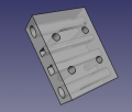
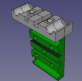
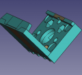
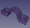
![[10] Short Idler Side - 75k - FreeCAD - File:Universal Axis Idler Side short version.fcstd. STL - File:Universal Axis Idler Side short version.stl.](/images/thumb/a/ae/Idlershort.jpg/120px-Idlershort.jpg) [10] Short Idler Side - 75k - FreeCAD - File:Universal Axis Idler Side short version.fcstd. STL - File:Universal Axis Idler Side short version.stl.
[10] Short Idler Side - 75k - FreeCAD - File:Universal Axis Idler Side short version.fcstd. STL - File:Universal Axis Idler Side short version.stl.
Half carriage: File:Axis half carriage.fcstd. STL - File:Axis half carriage.stl
Y Axis from v19.06. - FreeCAD - File:Yaxisfrom1906.fcstd.
X axis from v19.06. - FreeCAD - File:Xaxisfrom1906.fcstd.
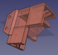
Carriage motor merge. - FreeCAD - File:Carriage motor merge.fcstd. STL - File:Carriage motor merge.stl
Carriage half-carriage merge. - FreeCAD - File:Carriage halfcarriage merge.fcstd. STL - File:Carriage halfcarriage merge.stl.
Carriage extruder bracket merge. - FreeCAD - File:Integrated carriage.fcstd. STL - File:Integrated carriage.stl
Frame clip - FreeCAD - File:Frameclip.fcstd. STL - File:Frameclip.stl
'Carriage to bed connection. - FreeCAD - File:Carriage idler merge.fcstd. STL - File:Carriagebed.stl
'Motor side with clip. - FreeCAD - File:Motorwithclip.fcstd. STL - File:Motorwithclip.stl
'Idler side with clip. - FreeCAD - File:Idlerwithclip.fcstd. STL - File:Idlerwithclip.stl
'Cable clip. - FreeCAD - File:Cableclip.fcstd. STL - File:Cableclip.stl
'Cable clip for end of axis nut catch. - FreeCAD - File:Cableclip2.fcstd. STL - File:Cableclip2.stl
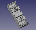
![[10] Belt Holding Peg - FreeCAD original size - File:Peg 8mm rods.fcstd. STL at 85% size, works well - File:Peg 8mm rods.stl](/images/thumb/a/a5/Peg85.jpg/120px-Peg85.jpg) [10] Belt Holding Peg - FreeCAD original size - File:Peg 8mm rods.fcstd. STL at 85% size, works well - File:Peg 8mm rods.stl
[10] Belt Holding Peg - FreeCAD original size - File:Peg 8mm rods.fcstd. STL at 85% size, works well - File:Peg 8mm rods.stl
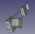
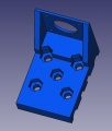
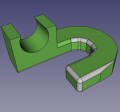
![Spool Holder. File: File:Spoolholder.stl Link for more types of these joints - [1]](/images/thumb/d/d6/Spoolholderjoint.jpg/120px-Spoolholderjoint.jpg) Spool Holder. File: File:Spoolholder.stl Link for more types of these joints - [1]
Spool Holder. File: File:Spoolholder.stl Link for more types of these joints - [1]
Auto parallel piece. File: File:Autoparallel.fcstd File:Autoparallel.stl


![[10] Motor Side of Axis - 221k - FreeCAD -File:Universal axis motor side.fcstd. STL - File:Universal axis motor side.stl](/wiki/File:Motorside.jpg)

![[10] Short Idler Side - 75k - FreeCAD - File:Universal Axis Idler Side short version.fcstd. STL - File:Universal Axis Idler Side short version.stl.](/wiki/File:Idlershort.jpg)


![[10] Belt Holding Peg - FreeCAD original size - File:Peg 8mm rods.fcstd. STL at 85% size, works well - File:Peg 8mm rods.stl](/wiki/File:Peg85.jpg)
![Spool Holder. File: File:Spoolholder.stl Link for more types of these joints - [1]](/wiki/File:Spoolholderjoint.jpg)
Control Panel
See more at 3D Printer Control Panel

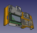
Control Panel - FreeCAD -File:Controlpanel v1904.fcstd. Bent panel STL - File:Bentpanel v1904.stl

BOM
Quick attach wiring.
Connector 1
| Extruder part | N° | Wire color |
|---|---|---|
| Heat sink fan | 1 | + red |
| 2 | - black | |
| Thermistor | 3 | orange |
| 4 | white | |
| Heater element | 5 | green |
| 6 | yellow | |
| Active cooling fan | 7 | + brown |
| 8 | - blue |
Connector 2
| Extruder part | N° | Wire color |
|---|---|---|
| Z-probe | 1 | brown |
| 2 | blue | |
| 3 | black | |
| Extruder stepper motor | 4 | green |
| 5 | yellow | |
| 6 | orange | |
| 7 | red |
Bugs
- Card slot 3D print - notch too large, card can be pushed in behind the slot
- Get rid of STOP PRINT from menu - can hit it accidentally during long print
- Fix belt hole in carriage to motor
- Fix carriage to idler placement
- Improvement - Flexible surface for popping prints right off
Links
- D3D v19.06 - other parts
- Y Axis Auto-Parallel - Details
- 120v Heatbed - detailed assembly photos
Product
Build Instructions
Wiring
By Irvin:
Control Panel Wiring and Test
This is part of a quality control sequence, which requires identificiation of all wires: Final_Five_Minute_Control_Panel_Test
Firmware
Links
- Eric's proposal - Eric D3D Pro Proposal
- D3D Production Records
- D3D_Pro_Product_Release