D3D Pro: Difference between revisions
No edit summary |
(→Links) |
||
| (66 intermediate revisions by 3 users not shown) | |||
| Line 1: | Line 1: | ||
{{OrigLang}} | {{OrigLang}} | ||
{{Hint|We now make [[D3D Pro 3]] with an 18" print bed.}} | |||
=Intro= | |||
[[File:d3dpro.jpg|500px]] | [[File:d3dpro.jpg|500px]] | ||
'''You can get a ready-to-build kit at https://www.opensourceecology.org/d3d-pro/''' | '''You can get a ready-to-build kit at https://www.opensourceecology.org/d3d-pro/''' | ||
='''Development'''= | |||
{| class="wikitable" | |||
|+ Development Template | |||
! | |||
! Description | |||
! Link to Work Product | |||
! % | |||
|- | |||
! scope=row | | |||
| '''DESIGN''' || || | |||
|- | |||
! scope=row | 1 | |||
| [[Requirements + Value Proposition]] || [[D3D Pro Requirements + Value Proposition]] || {{{1}}} | |||
|- | |||
! scope=row | 2 | |||
| [[Industry_Standards]] || [[D3D Pro Industry Standards]] || {{{2}}} | |||
|- | |||
! scope=row | 3 | |||
| [[Conceptual Design]] || [[D3D Pro Conceptual Design]] || {{{3}}} | |||
|- | |||
! scope=row | 4 | |||
| [[Module Breakdown]] || [[D3D Pro Module Breakdown]] || {{{4}}} | |||
|- | |||
! scope=row | 5 | |||
| [[3D CAD]] || [[D3D Pro 3D CAD]] || {{{5}}} | |||
|- | |||
! scope=row | 6 | |||
| [[Calculations]] || [[D3D Pro Calculations]] || {{{6}}} | |||
|- | |||
! scope=row | 7 | |||
| [[Electronics Design]] || [[D3D Pro Electronics Design]] || {{{7}}} | |||
|- | |||
! scope=row | 8 | |||
| [[Wiring and Plumbing]] || [[D3D Pro Wiring and Plumbing]] || {{{8}}} | |||
|- | |||
! scope=row | 9 | |||
| [[Software]] || [[D3D Pro Software]] || {{{9}}} | |||
|- | |||
! scope=row | | |||
| '''BILL OF MATERIALS || || | |||
|- | |||
! scope=row | 10 | |||
| [[BOM]] || [[D3D Pro BOM]] || {{{10}}} | |||
|- | |||
! scope=row | 11 | |||
| [[vBOM]] || [[D3D Pro vBOM]] || {{{11}}} | |||
|- | |||
! scope=row | 12 | |||
| [[CAM Files]] || [[D3D Pro CAM Files]] || {{{12}}} | |||
|- | |||
! scope=row | 13 | |||
| [[Cut List]] || [[D3D Pro Cut List]] || {{{13}}} | |||
|- | |||
! scope=row | | |||
| '''BUILD''' || || | |||
|- | |||
! scope=row | 14 | |||
| [[Build Instructions]] || [[D3D Pro Build Instructions]] || {{{14}}} | |||
|- | |||
! scope=row | 15 | |||
| [[Fabrication Drawings]] || [[D3D Pro Fabrication Drawings]] || {{{15}}} | |||
|- | |||
! scope=row | 16 | |||
| [[Exploded Part Diagram]] || [[D3D Pro Exploded Part Diagram]] || {{{16}}} | |||
|- | |||
! scope=row | 17 | |||
| [[Production Engineering]] || [[D3D Pro Production Engineering]] || {{{17}}} | |||
|- | |||
! scope=row | | |||
| '''DATA COLLECTION''' || || | |||
|- | |||
! scope=row | 18 | |||
| [[Build Pictures and Video]] || [[D3D Pro Build Pictures and Video]] || {{{18}}} | |||
|- | |||
! scope=row | 19 | |||
| [[Data Collection]] || [[D3D Pro Data Collection]] || {{{19}}} | |||
|- | |||
! scope=row | 20 | |||
| [[Future Work]] || [[D3D Pro Future Work]] || {{{20}}} | |||
|} | |||
=CAD= | =CAD= | ||
[[File:carriagemotor.png|100px]][[File:yaxisfroma1906.png|100px]][[File:14angleframe.png|100px]][[File:d3d1911xaxis.png|100px]] | [[File:carriagemotor.png|100px]][[File:yaxisfroma1906.png|100px]][[File:14angleframe.png|100px]][[File:d3d1911xaxis.png|100px]] | ||
[[File:assy1.png|100px]][[File:carriagemotor.png|100px]][[File:carriagemotor2.png|100px]][[File:carriagehalfcarriage.png|100px]][[File:frameclip.png|100px]][[File:carriageidler.png|100px]][[File:motorwithclip.png|100px]][[File:idlerwithclip.png|100px]][[File:cableclip.png|100px]][[File:motorwithhanger.png|100px]][[File:d3dcableorg_loop.png|100px]][[File:loomclip.png|100px]] | [[File:assy1.png|100px]][[File:carriagemotor.png|100px]][[File:carriagemotor2.png|100px]][[File:carriagehalfcarriage.png|100px]][[File:frameclip.png|100px]][[File:carriageidler.png|100px]][[File:motorwithclip.png|100px]][[File:idlerwithclip.png|100px]][[File:cableclip.png|100px]][[File:motorwithhanger.png|100px]][[File:d3dcableorg_loop.png|100px]][[File:loomclip.png|100px]][[File:updatedforyconnex.jpg|100px]][[File:updatedgantryfory.jpg|100px]][[File:widenedmotor.png|100px]][[File:widenedidler.png|100px]][[File:truncatedwidenedmotor.png|100px]][[File:autoparallel.png|100px]][[File:withsidehole.png|100px]][[File:xidlerside.png|100px]] | ||
<gallery perrow=6> | <gallery perrow=6> | ||
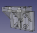
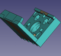
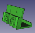
File: | File:updatedgantryfory.jpg|'''Updated gantry for D3D Pro. ''' - FreeCAD -[[File:d3d1911.fcstd]] | ||
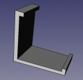
File:14angleframe.png|'''16" Frame ''' - FreeCAD -[[File:frame16.fcstd]] | File:14angleframe.png|'''16" Frame ''' - FreeCAD -[[File:frame16.fcstd]] | ||
| Line 21: | Line 131: | ||
File:rightcorner.png|'''Angle Connector with axis mount, right side.''' - FreeCAD - [[File:rightcorner.fcstd]]. Finished STL - [[File:rightcorner.stl]] | File:rightcorner.png|'''Angle Connector with axis mount, right side.''' - FreeCAD - [[File:rightcorner.fcstd]]. Finished STL - [[File:rightcorner.stl]] | ||
File:Motorside.jpg|[[File:check.png]]'''[10] Motor Side of Axis''' - 221k - FreeCAD -[[File:Universal_axis_motor_side.fcstd]]. STL - [[File:Universal axis motor side.stl]] | |||
File:simplecarriage.png|Universal axis carriage: [[File:Universal_axis_carriage_side.fcstd]]. STL - [[File:Universal_axis_carriage_side.stl]] | |||
File:idlershort.jpg|[[File:check.png]]'''[10] Short Idler Side''' - 75k - FreeCAD - [[File:Universal_Axis_Idler_Side_short_version.fcstd]]. STL - [[File:Universal_Axis_Idler_Side_short_version.stl]]. | |||
File:axis_half_carriage.png|Half carriage: [[File:axis_half_carriage.fcstd]]. STL - [[File:axis_half_carriage.stl]] | |||
File:yaxisfroma1906.png|'''Y Axis from v19.06.''' - FreeCAD - [[File:yaxisfrom1906.fcstd]]. | File:yaxisfroma1906.png|'''Y Axis from v19.06.''' - FreeCAD - [[File:yaxisfrom1906.fcstd]]. | ||
File: | File:updatedforyconnex.jpg|'''X axis from v19.06.''' - FreeCAD - [[File:xaxisfrom1906.fcstd]]. | ||
File:carriagemotor.png|'''Carriage motor merge.''' - FreeCAD - [[File:Carriage_motor_merge.fcstd]]. STL - [[File:Carriage_motor_merge.stl]] | File:carriagemotor.png|'''Carriage motor merge.''' - FreeCAD - [[File:Carriage_motor_merge.fcstd]]. STL - [[File:Carriage_motor_merge.stl]] | ||
File: | File:xidlerside.png|'''Carriage half-carriage merge.''' - FreeCAD - [[File:Carriage_halfcarriage_merge.fcstd]]. STL - [[File:Carriage_halfcarriage_merge.stl]]. | ||
File:Integrated_carriage.jpg|'''Carriage extruder bracket merge.''' - FreeCAD - [[File:Integrated_carriage.fcstd]]. STL - [[File:Integrated_carriage.stl]] | File:Integrated_carriage.jpg|'''Carriage extruder bracket merge.''' - FreeCAD - [[File:Integrated_carriage.fcstd]]. STL - [[File:Integrated_carriage.stl]] | ||
| Line 37: | Line 155: | ||
File:carriageidler.png|'''Carriage to bed connection.'' - FreeCAD - [[File:Carriage_idler_merge.fcstd]]. STL - [[File:carriagebed.stl]] | File:carriageidler.png|'''Carriage to bed connection.'' - FreeCAD - [[File:Carriage_idler_merge.fcstd]]. STL - [[File:carriagebed.stl]] | ||
File: | File:truncatedwidenedmotor.png|'''Motor side with clip.'' - FreeCAD - [[File:motorwithclip.fcstd]]. STL - [[File:motorwithclip.stl]] | ||
File: | File:widenedidler.png|'''Idler side with clip.'' - FreeCAD - [[File:idlerwithclip.fcstd]]. STL - [[File:idlerwithclip.stl]] | ||
File:cableclip.png|'''Cable clip.'' - FreeCAD - [[File:cableclip.fcstd]]. STL - [[File:cableclip.stl]] | File:cableclip.png|'''Cable clip.'' - FreeCAD - [[File:cableclip.fcstd]]. STL - [[File:cableclip.stl]] | ||
| Line 45: | Line 163: | ||
File:loomclip.png|'''Cable clip for end of axis nut catch.'' - FreeCAD - [[File:cableclip2.fcstd]]. STL - [[File:cableclip2.stl]] | File:loomclip.png|'''Cable clip for end of axis nut catch.'' - FreeCAD - [[File:cableclip2.fcstd]]. STL - [[File:cableclip2.stl]] | ||
File:peg85.jpg|[[File:check.png]]'''[10] Belt Holding Peg''' - FreeCAD original size - [[File:peg_8mm_rods.fcstd]]. STL at 85% size, works well - [[File:peg_8mm_rods.stl]] | |||
File:spoolholderjoint.jpg|[[File:check.png]]'''Spool Holder.''' File: [[File:spoolholder.stl]] Link for more types of these joints - [https://www.thingiverse.com/thing:2300366] | |||
File:withsidehole.png|'''Auto parallel piece.''' File: [[File:autoparallel.fcstd]] [[File:autoparallel.stl]] | |||
</gallery> | </gallery> | ||
==Control Panel== | |||
See more at [[3D Printer Control Panel]] | |||
[[File:ontrolpanelseated.png|100px]] | |||
<gallery perrow=6> | |||
File:controlpanelwithmounts_v1904.png|'''Control Panel''' - FreeCAD -[[File:controlpanel_v1904.fcstd]]. Bent panel STL - [[File:Bentpanel_v1904.stl]] | |||
</gallery> | |||
=BOM= | |||
<html><iframe src="https://docs.google.com/spreadsheets/d/e/2PACX-1vTIQ01MZArBSn5UUBr6i5xwCbhUPxCI3LuZZQNzXRwG4pbZIMlQvOzuNcvzS-RPGBU_7cylUtVp0avm/pubhtml?widget=true&headers=false" height=600 width=900></iframe></html> | |||
[https://docs.google.com/spreadsheets/d/1rHkfwE_CMwePcAg9vuHtV2jooIJ8hGihrCFGNJlBpog/edit#gid=1571230577 edit] | |||
Notes: BOM must be updated for Universal Gearless Extruder | |||
==BOM Notes== | |||
*A 4x8 sheet of 16 ga steel weighs 80 lb. | |||
*A 4x8 sheet produces 24 strips of 8' length - or 192' of strip for 24 cuts | |||
*Cutting cost? $1 at [[Metal by the Foot]]? | |||
*A 4x8 costs $114 at Metal by the Foot. | |||
=Quick attach wiring.= | =Quick attach wiring.= | ||
| Line 126: | Line 273: | ||
=Links= | =Links= | ||
*[[D3D v19.06]] - other parts | *[[D3D v19.06]] - other parts | ||
*[https://wiki.opensourceecology.org/wiki/Y_Axis_Auto-parallel Y Axis Auto-Parallel] - Details | |||
*[https://www.facebook.com/marcin.jakubowski.378/posts/10217670033399780?hc_location=ufi 120v Heatbed] - detailed assembly photos | |||
=Product= | =Product= | ||
*See [[D3D Pro Product Page]] | *See [[D3D Pro Product Page]] | ||
=Build Instructions= | |||
<html><iframe src="https://docs.google.com/presentation/d/e/2PACX-1vRTZ_J2ZcWe_DxW_thJXiN7v6QCUnfuZvMVb9y3bwAHTTR_NpnPpZFsFAb7qiZK6YomPdz4DXPgzUK5/embed?start=false&loop=false&delayms=3000" frameborder="0" width="408" height="557" allowfullscreen="true" mozallowfullscreen="true" webkitallowfullscreen="true"></iframe></html> | |||
[https://docs.google.com/presentation/d/1r8DquY2ALFOj52tWEXR-pdAAjPTwBV31mBtXbBKX_NI/edit#slide=id.g4303b70038_0_0 edit] | |||
=Wiring= | |||
By Irvin: | |||
<html><iframe src="https://www.facebook.com/plugins/post.php?href=https%3A%2F%2Fwww.facebook.com%2Fmarcin.jakubowski.378%2Fposts%2F10219191144266601&width=500" width="500" height="578" style="border:none;overflow:hidden" scrolling="no" frameborder="0" allowTransparency="true" allow="encrypted-media"></iframe></html> | |||
=Control Panel Wiring and Test= | |||
This is part of a quality control sequence, which requires identificiation of all wires: [[Final_Five_Minute_Control_Panel_Test]] | |||
=Testimonials= | |||
"The most immediate thing I am hoping to use the printer for is actually to do with the pen plotter hack - I'm working on a project where we produce pen plotter drawings generated from code and I thought a universal axis to be a far more flexible solution. -Jon S, UK." | |||
can we get benchmarks/video reviews? | |||
=Links= | =Links= | ||
*'''[[D3D Genealogy]]''' - bleeding edge version as of May, 2020 is [[D3D_v20.04.27]] with 18" print bed. | |||
*Eric's proposal - [[Eric D3D Pro Proposal]] | *Eric's proposal - [[Eric D3D Pro Proposal]] | ||
*[[D3D Pro Order Response]] | |||
*[[D3D Production Records]] | |||
[[Category: D3D]] | [[Category: D3D]] | ||
*[[D3D_Pro_Product_Release]] | |||
=Hit Counter Added June 3, 2022= | |||
<html><div class="powr-hit-counter" id="62fd9bb1_1654285495"></div><script src="https://www.powr.io/powr.js?platform=html"></script></html> | |||
Latest revision as of 19:45, 3 June 2022
![]() Hint: We now make D3D Pro 3 with an 18" print bed.
Hint: We now make D3D Pro 3 with an 18" print bed.
Intro

You can get a ready-to-build kit at https://www.opensourceecology.org/d3d-pro/
Development
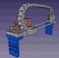
CAD


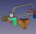
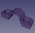
Updated gantry for D3D Pro. - FreeCAD -File:D3d1911.fcstd
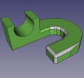
16" Frame - FreeCAD -File:Frame16.fcstd
Angle Connector. - FreeCAD with McMaster 6 mm nut -File:Angleconnector.fcstd. Finished STL - File:Anglecorner.stl
Angle Connector with axis mount, left side. - FreeCAD - File:Leftcorner.fcstd. Finished STL - File:Leftcorner.stl
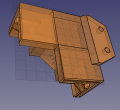
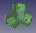
Angle Connector with axis mount, right side. - FreeCAD - File:Rightcorner.fcstd. Finished STL - File:Rightcorner.stl
![[10] Motor Side of Axis - 221k - FreeCAD -File:Universal axis motor side.fcstd. STL - File:Universal axis motor side.stl](/images/thumb/4/45/Motorside.jpg/120px-Motorside.jpg)
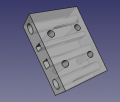
 [10] Motor Side of Axis - 221k - FreeCAD -File:Universal axis motor side.fcstd. STL - File:Universal axis motor side.stl
Universal axis carriage: File:Universal axis carriage side.fcstd. STL - File:Universal axis carriage side.stl
![[10] Short Idler Side - 75k - FreeCAD - File:Universal Axis Idler Side short version.fcstd. STL - File:Universal Axis Idler Side short version.stl.](/images/thumb/a/ae/Idlershort.jpg/120px-Idlershort.jpg) [10] Short Idler Side - 75k - FreeCAD - File:Universal Axis Idler Side short version.fcstd. STL - File:Universal Axis Idler Side short version.stl.
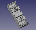
[10] Short Idler Side - 75k - FreeCAD - File:Universal Axis Idler Side short version.fcstd. STL - File:Universal Axis Idler Side short version.stl.
Half carriage: File:Axis half carriage.fcstd. STL - File:Axis half carriage.stl
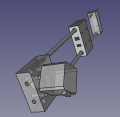
Y Axis from v19.06. - FreeCAD - File:Yaxisfrom1906.fcstd.
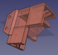
X axis from v19.06. - FreeCAD - File:Xaxisfrom1906.fcstd.
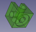
Carriage motor merge. - FreeCAD - File:Carriage motor merge.fcstd. STL - File:Carriage motor merge.stl
Carriage half-carriage merge. - FreeCAD - File:Carriage halfcarriage merge.fcstd. STL - File:Carriage halfcarriage merge.stl.
Carriage extruder bracket merge. - FreeCAD - File:Integrated carriage.fcstd. STL - File:Integrated carriage.stl
Frame clip - FreeCAD - File:Frameclip.fcstd. STL - File:Frameclip.stl
'Carriage to bed connection. - FreeCAD - File:Carriage idler merge.fcstd. STL - File:Carriagebed.stl
'Motor side with clip. - FreeCAD - File:Motorwithclip.fcstd. STL - File:Motorwithclip.stl
'Idler side with clip. - FreeCAD - File:Idlerwithclip.fcstd. STL - File:Idlerwithclip.stl
'Cable clip. - FreeCAD - File:Cableclip.fcstd. STL - File:Cableclip.stl
'Cable clip for end of axis nut catch. - FreeCAD - File:Cableclip2.fcstd. STL - File:Cableclip2.stl
![[10] Belt Holding Peg - FreeCAD original size - File:Peg 8mm rods.fcstd. STL at 85% size, works well - File:Peg 8mm rods.stl](/images/thumb/a/a5/Peg85.jpg/120px-Peg85.jpg) [10] Belt Holding Peg - FreeCAD original size - File:Peg 8mm rods.fcstd. STL at 85% size, works well - File:Peg 8mm rods.stl
[10] Belt Holding Peg - FreeCAD original size - File:Peg 8mm rods.fcstd. STL at 85% size, works well - File:Peg 8mm rods.stl
![Spool Holder. File: File:Spoolholder.stl Link for more types of these joints - [1]](/images/thumb/d/d6/Spoolholderjoint.jpg/120px-Spoolholderjoint.jpg) Spool Holder. File: File:Spoolholder.stl Link for more types of these joints - [1]
Spool Holder. File: File:Spoolholder.stl Link for more types of these joints - [1]
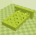
Auto parallel piece. File: File:Autoparallel.fcstd File:Autoparallel.stl


![[10] Motor Side of Axis - 221k - FreeCAD -File:Universal axis motor side.fcstd. STL - File:Universal axis motor side.stl](/wiki/File:Motorside.jpg)

![[10] Short Idler Side - 75k - FreeCAD - File:Universal Axis Idler Side short version.fcstd. STL - File:Universal Axis Idler Side short version.stl.](/wiki/File:Idlershort.jpg)


![[10] Belt Holding Peg - FreeCAD original size - File:Peg 8mm rods.fcstd. STL at 85% size, works well - File:Peg 8mm rods.stl](/wiki/File:Peg85.jpg)
![Spool Holder. File: File:Spoolholder.stl Link for more types of these joints - [1]](/wiki/File:Spoolholderjoint.jpg)
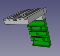
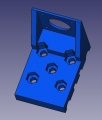
Control Panel
See more at 3D Printer Control Panel

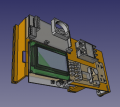
Control Panel - FreeCAD -File:Controlpanel v1904.fcstd. Bent panel STL - File:Bentpanel v1904.stl

BOM
Notes: BOM must be updated for Universal Gearless Extruder
BOM Notes
- A 4x8 sheet of 16 ga steel weighs 80 lb.
- A 4x8 sheet produces 24 strips of 8' length - or 192' of strip for 24 cuts
- Cutting cost? $1 at Metal by the Foot?
- A 4x8 costs $114 at Metal by the Foot.
Quick attach wiring.
Connector 1
| Extruder part | N° | Wire color |
|---|---|---|
| Heat sink fan | 1 | + red |
| 2 | - black | |
| Thermistor | 3 | orange |
| 4 | white | |
| Heater element | 5 | green |
| 6 | yellow | |
| Active cooling fan | 7 | + brown |
| 8 | - blue |
Connector 2
| Extruder part | N° | Wire color |
|---|---|---|
| Z-probe | 1 | brown |
| 2 | blue | |
| 3 | black | |
| Extruder stepper motor | 4 | green |
| 5 | yellow | |
| 6 | orange | |
| 7 | red |
Bugs
- Card slot 3D print - notch too large, card can be pushed in behind the slot
- Get rid of STOP PRINT from menu - can hit it accidentally during long print
- Fix belt hole in carriage to motor
- Fix carriage to idler placement
- Improvement - Flexible surface for popping prints right off
Links
- D3D v19.06 - other parts
- Y Axis Auto-Parallel - Details
- 120v Heatbed - detailed assembly photos
Product
Build Instructions
Wiring
By Irvin:
Control Panel Wiring and Test
This is part of a quality control sequence, which requires identificiation of all wires: Final_Five_Minute_Control_Panel_Test
Testimonials
"The most immediate thing I am hoping to use the printer for is actually to do with the pen plotter hack - I'm working on a project where we produce pen plotter drawings generated from code and I thought a universal axis to be a far more flexible solution. -Jon S, UK."
can we get benchmarks/video reviews?
Links
- D3D Genealogy - bleeding edge version as of May, 2020 is D3D_v20.04.27 with 18" print bed.
- Eric's proposal - Eric D3D Pro Proposal
- D3D Pro Order Response
- D3D Production Records
- D3D_Pro_Product_Release