Universal Rotor
| Universal Rotor | ||
|---|---|---|
| Home | Research & Development | Bill of Materials | Manufacturing Instructions | User's Manual | User Reviews | 
| |
| ||||||||||||||||||||||||||
Development
Overview
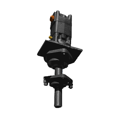
The Universal Rotor(UR) is a standardized, heavy duty, modular, scalable rotor for utility, construction, and manufacturing purposes. The current iteration inolves a triple interface mount that allows for various tasks (work) to be accomplished by harnessing the high rotational torque and speeds generated by a hydraulic motor (or electric motor, etc). This is a fundamental component for any GVCS machine that uses a motor. It provides modularity, redundancy, scalability and represents a significant cost reduction by being able to use only one motor to power many machines. Examples are: Attaching the wheels to Lifetrac and powering them; a mower, auger or slurry mixer for Lifetrac; the saw blades on the Saw Mill. Attaching a lathe chuck and adding the 2" Universal Axis with Universal Controller turns it into a CNC lathe. It can be used to drive heavy slow rotors, such as a plastic shredder, pelletizer, or with geardown - a rock grinder. It connected to rollers, this can drive metal rolling equipment.
Build
Details
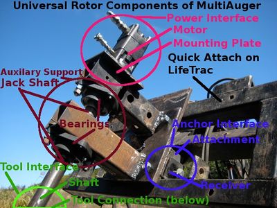
This triple interface that allows the UR to harness motor power has 3 interfaces which each have 2 sides to it. The following are the three interfaces with the 2 sides of each interface in parenthesis:
1) Anchor Interface: (Receiver & Attachment)
Is the stationary side of the interface and serves to 'anchor' the UR to a solid object. This is done by connecting/inserting the Attachment on the UR to the Receiver on the solid object.
-Allows the shaft(tool) to be mounted at multiple angles in relation to the machine. This makes the UR useful for vertical shaft applications like an earth auger or mower and horizontal shaft applications like a wheel trencher or wheel drive that powers the LifeTrac. This can be accomplished with a single square tube which is rotated 90 degrees and reattached.
-Another axis of rotation can be accomplished by adding multiple tubes to either the receiver side of the interface at angles to the primary one. It could also be accomplished by using an angle adapter tube.
2) Power Interface: (Motor & Mounting Plate)
Mounts the motor to the mounting plate which is part of the UR's structure. In addition to how the motor attaches, this interface also considers the space that various motors would need and ensures that the rest of the UR structure nor the machine it is attached to doesn't interfere with the space need for motors. Additionally, space for motor removal and the connection and protection of hydraulic lines needs consideration. There are four common motor mount styles: Face, Wheel Motor(body) Tail, Base. The focus of the UR will be face and wheel motor mounting for hydraulic motors. For face mounting the UR will utilize SAE hydraulic motor mounting dimensions since the GVCS hydraulic motor will likely adopt these and SAE motors are currently being used by OSE and readily available. Wheel Motor Mounting dimensions are less standardized. In either case by starting with one of the largest SAE face mounting patterns, adapter plates can be bolted to that pattern to accommodate smaller face mount and wheel motors.
3)Tool Interface: (shaft connection & tool connection)
Connects the rotating shaft of the motor to the tool to be rotated. There might be adapters for different applications. For example a tire rim on the LifeTrac might bolt to the same mount as an 8' diameter wheel trencher. But that might be to large mount for an auger or a 16” cold saw blade. The primary mount needs to be sufficient to handle the forces for all applications, and then smaller adapter mount attached to it. The primary mount should be as compact as possible but still quickly attachable, perfectly concentric and have zero slop. If a wheel style mount is used, there are two types, hub concentric(w/flat lug nuts) and stud centric(with tapered/cone lug nuts)
1,2&3) All three interfaces must individually be:
-Scalable in thickness or dimension for applications with higher forces
The Universal Rotor as a whole must be:
-Withstand extreme radial, axial and twisting(in relation to the motor shaft) generated by all the applications for which it will be used for.
-Light as possible to be managed by hand
-Compact
Other Considerations:
1) Accomodating for gearing and multiple motors
Because there may be a limit to the amount of power or speed that available motors produce, gearing or the use of multiple motors may be needed when the tool requires more power or speed. For gearing with a single motor this can be accomplished by breaking the direct connection between the motor shaft and the tool and routing the power flow thru a gear reduction (chain & sprockets) first. Or additional motors could be added by keeping a direct connection between the tool and motor but mounting a 2nd motor and connecting its shaft to the shaft of the primary motor via chain. However, if the speed and power of the motor is suitable for the application it is best to have a straight connection to the tool.
Decisions:
1) Wheel Motors(bearings built in) or Jack Shaft(with auxiliary bearing support structure)?
Due to the wide range of applications, the UR needs to handle high axial and radial forces. Wheel motors have larger bearings then standard hydraulic motors to resist these much higher forces. Wheel motors are available commercially that will handle the radial and axial loads of all current GVCS applications. However wheel motors are low speed. High speed motors don't usually have such large bearings. While generally you don't need large bearings while doing high speed operations, an accident, such as hitting a tree stump with a high speed mower blade may damage a motor with smaller bearings. Adding a separate shaft(jack shaft) that is supported by separate bearings between the motor shaft and tool effectively isolates the motor shaft and bearings from any radial forces, as well as axial forces if properly designed. This is the design currently being used on LifeTrac III and the MultiAuger. The current design on the LifeTrac is excessive in length and has some proven and suspected issues. A much shorter and simpler jack shaft setup should be possible that is more comparable to a wheel motor in size. If a jack shaft setup is chosen as the primary UR setup, it should be designed so that only wheel motor can be used instead with minimal variation(or none) for replicators who choose to do so.
The current quick connect wheel assembly with the jack shaft and auxilary bearings was a necessary component when the LifeTrac was powered by the original weaker drive motors. However during the redesign, new 15,000 Inch Pound Motors were purchased which are actually wheel motors that have a much higher carrying capicity which means the whole jack shaft assembly might not even be necessary as the motor is designed to handle up to 11,000 of radial load per the specs provided by the manufacturer. It has already been proposed by Marcin that the wheel connect be redesigned to address several issues, but in reality, it can actually be completely ommited without having to purchase additional motors.
Comparison:
Wheel Motor UR Advantages:
-Much more compact, lightweight, cheaper and very quick to build
-Sealed & lubricated bearings
-Industry Proven
-Less parts to break or wear out
Auxiliary Bearing UR Advantages:
-Can remove the motor with out disconnecting the tool(or the tire when used as wheel drive)
-More motor choices (especially rpm)
-Can use a gear reduction or multiple motors much easier
2) Tapered or Roller Bearings?
If a jack shaft with auxiliary bearings are to be used, will it use tapered bearings to resist axial thrust or just thrust washers? Thrust washers are not good, especially if the tool is hanging, being pushed on(ie. Auger) or anything with constant side loading. The only reason not to use tapered bearings is because they are harder to make and mount out of raw steel and if a suitable off-the-shelf setup might not be found in the mean time They also require preloading of the two opposed tapered bearings against each other by means of a threaded shaft or a press fit. One source might be preassembled “4x4 truck hubs” as found on ebay. A tapered bearing solution will almost always be more compact and robust.
Before spending much time on one particular design, it will help to imagine that design being used in each of the applications that the UR is to be used in.
Applications with the LifeTrac for the UR:
Other GVCS machines with UR applications:
Product Ecology
Uses
 Induction Furnace - Steel
 CNC Torch Table - Parts
 Tractor - Mounting
 Power Cube - Power
 Hydraulic Motor - Power
Mounts
- String Trimmer,
- Tree Planting auger,
- Lathe,
- drill press,
- soil line cutting rotor,
- honey extractor.
- Trencher
Status
The Universal Rotor is currently in the prototyping phase of product development.
The hydraulic motor is interchangeable, and so far, a 32 cu in and a 6 cu in motors have been used which have a quick mounting plate with 2 3/4" bolts for hold-down. The assembly can be mounted either horizontally or vertically by bolting to a back plate accordingly.
Future prototype designs aim to improve structural integrity, increased ease of mounting for LifeTrac, and improved interchangeability of motors.
Actions are logged in Universal Rotor Log.
Links
- Universal Rotor Construction Set
- Universal Rotor 2 - Modular Wheel Units - are one implementation of the Universal Rotor. Also used in track drive.
- Deka-kW VAWT Wind Turbine - another implementation of the Universal Rotor
- Blog Post
- CAD
- Institution of Engineering and Technology


