Power Cube/Manufacturing Instructions
| Power Cube | ||
|---|---|---|
| Home | Research & Development | Bill of Materials | Manufacturing Instructions | User's Manual | User Reviews | 
| |
| |||||||||||
Overview

Intro to Power Cube Construction Script [[1]]
Preparation
Safety
- Hearing Protection
- Eye Protection
- Steel Toe Boots
- Welding
- Gloves
- Hood
- Apron/Jacket
Workspace
This section describes the various workspace areas that we have found to be useful in fabricating the Power Cube. It is provided as a suggestion for preparing your work area.
- Storage: For raw steel and parts
- Cutting Area: For use with cutting torch - Made from non-flammable materials
- Welding Table: Usually steel, suitable for use with arc welder (MIG, TIG, stick, etc)
- Ventilation for cutting / welding areas: Especially when working with galvanised steel
Tools
- Welder
- Angle Grinder
- Hand Tools
- Crescent wrench
- Socket set
- Hammer
- Metal Cutting Tools
- Bandsaw
- Chopsaw
- Torch
- Paint Tools
- Gravity Fed Paint Sprayer
- Air compressor
Subassembly Fabrication
- The purpose of this section is to cut the raw steel into required lengths and shapes as required for final assembly.
- These step includes drilling and cutting steel up to 3/8” in thickness.
Engine & Hydraulic Pump mounts
- ¼” x 8” x 12” Plate
- ¼” x 8” x 9” Plate
- ¼” x 2” x 2” x 8” Angle
- ¼” x 2” x 2” x 29” Angle
- ¼” x 8” x 8” Plate

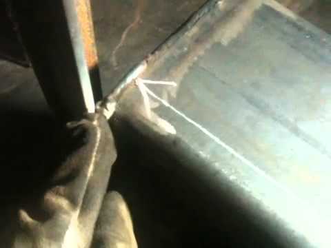
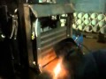
Torching of engine mounts:
And, torching the last of the 9 power cube engine mount plate holes:
Quick attach mounts
- [2] 3/8” x 4” x 27” Plates

Fuel tank
- [2] ¼” x 4” x 8” Plates
- 4” x 8” x 14 ½” Tube
- ¼” x 2” x 24” Plate
- All welds assembling the tank must be quality welds, as they must not leak. Be careful not to “over weld” the tank to the mount.
- Clean the inside of the ¼” x 4” x 8” tube and the two ¼” x 4” x 8” plates – anything left on these surfaces will end up in the gasoline and could clog the engine when started. Tack and weld the plates on each end of the tube, taking care to orient the top plate with the filler hole as shown in the diagram below.
- Weld the 1/4” tank flange to the smaller hole.

Oil Cooler Mount
- [2] ¼” x 2” x 24” Plates
- This is fan mount, not cooler mount. Holes in fan mount are missing. Length should be 23", not 24" -MJ
- [2] ¼” x 2” x 1” Plates
- [2] ¼” x 2” x 22” Plates (Note: the holes in these plates should be 6 inches apart, at 3" and 9" from bottom)

Note the correction on the dimensions of cooler mounts; hole can be oversized if washers are used:
Key Switches and Choke

Key switch mount location: on hydraulic tank side.
- [3] 1/8” x 2” x 2” x 2” Angle

Key Switch video:
Electrical cables
- Note: The connectors can be purchased from an auto parts store – be aware that they usually require a crimper to attach to the cables. Alternatively, 3/8” copper tubing can be used in 1 ½” long pieces instead. Strip 1 ½” insulation from the cable, fully insert fully into 1 ½” copper tube, flatten end with a hammer and drill hole.

- [2] 11” 1 gauge
- 8 ½” 1 gauge

Battery Mount
- [2] ¼” x 2” x 2” x 4 3/4” Angle
- [2] ¼” x 2” x 5/8” Plate

Cut pieces on bandsaw or metal cutoff saw.
Hydraulic reservoir
- [2] ¼” x 6” x 12”
- 6” x 12” x 27 ½” Tube
- 2” x 2 ¼” x 1/8” Tube
Clean tank components prior to welding
- Clean tank edges
- Clean inside of tank
- Clean-grind tank bungs
Welding Plates to Tube
- All welds assembling the reservoir must be quality welds that do not leak. Be careful not to “over weld” the reservoir.
- Tack and weld the 6” x 12” plates to both ends of the 6” x 12” tube.
Welding extension and flange
- Suction strainer
- Weld-in flange
- 2” x 2 ¼” x 1/8” tube

- Tack and weld the strainer extension tube to the tank, centered around the strainer hole.
- Insert the strainer into the flange and insert it into the strainer extension tube – verify that it slides without binding or bottoming and that the flange is flush with the end of the tube. Remove the strainer from the flange, then tack and weld the flange to the tank.
CAUTION: Keep the strainer away from the welding and flames, as its thin wires burn easily.

- Video of reservoirs after welding:
- After tack welding - measure location of engine mount 8 inches from inner edge of frame (not hydraulic tank) and 3 inches down from top of hydraulic tank:
Assembly
Power Cube assembly requires all the parts listed in the Bill Of Materials to be available and prepared as detailed in the “Fabrication” section (above). Assembly requires a welder (electric or torch) capable of welding metal 3/8” thick.
A Power Cube Jig can be very useful during the welding stage:

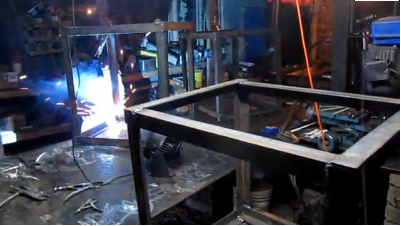
Power Cube Frame
- Position two ¼” x 2” x 2” x 29” pieces angle iron on top of two 27” angle pieces as shown below. Check that all joints are square, then tack and weld joints.

- With one welded rectangle on the bottom, position two 24” pieces outside corner joints as shown below. Check that the angles are square, then tack and weld. Note: The optional jig makes this much easier and accurate. Repeat the prior procedure and this one for another half of the frame assembly.

- Position the two half cubes together, then tack and weld. Inspect all corners to verify secure welds.

- Video of frame welding in progress:
- When finished, you'll have frames as shown in the following video:
Gas tank
- Screw the 1/4" hose barb into the 1/4 NPT flange welded into the gas tank.
- Perform a “soap bubble” test on the tank. Securely cover the larger hole (use something like strong tape), pressurize the tank using the smaller hole and cover the tank surface with soapy water. Look closely for new bubbles, mark any leaks and re-weld securely. Repeat soap bubble test if re-welded.
- Tack and weld the gas tank mount (¼” x 2” x 23” plate) to the frame. Position it so the gas tank is 1" from the nearest vertical angle iron support.
- Tack and weld the gas tank to the gas tank mount as shown below.

Tack weld and weld after clamping to frame:
Hydraulic tank
- Perform a “soap bubble” test on the tank by securely covering the larger hole (use something like strong tape), pressurizing the tank using the smaller hole and cover the tank surface with soapy water. Mark any leaks and re-weld securely. Repeat soap bubble test if re-welded.
- Cover holes to prevent debris from entering tank while welding.
- Secure to the frame using 6" clamps, then weld to the frame as shown with 4 1” welds. The tank is ¼” and it can be easily damaged by over-welding. Spacers may be needed on the sides near the top to keep everything snug.

Engine Mounts and Hydraulic Motor Mount
See Power Cube Tank Welding Procedure
Then review assembly order:
- Place the ¼” x 2” x 2” x 8” angle against the tank, 3" below the tank top and 8" from right edge of the tank as shown. Tack-weld it in place.
- Align the edges of the ¼” x 8” x 9” plate and the ¼” x 8” x 12” plate, forming a 90 degree angle as show below and weld the edge securely.

- Thread nuts on the four engine mounting bolts about 2/3 onto each bolt.
- Place engine on the 8" x 12" plate, insert the bolts into the engine mounting holes, with heads against the plate. Check for proper centering of the shaft in the hole and alignment of the bolts, then tack-weld the bolt heads to the plate. Remove engine and completely weld the bolts to the plate.
- Align the holes in the ¼” x 8” x 9” engine to those in the 29" angle iron as in the diagram below and secure with bolts, nuts and washers. Place the bolted assembly in the frame as shown and clamp to the frame in about the position shown.
- Align the holes in the ¼” x 8” x 12” engine plate to those in the 8" angle (above) and secure with two bolts, nuts and washers.
- Align the edges of the two engine plates so the corners just touch and tack the plates together.
- Tack the 29" angle iron in place to the two bottom angles.
- Attach engine.
- Check that all fits well, then weld angle iron and engine plates securely in place.

- Engine mounting
- NOTE: This may require some adaptation, as the bolt holes on engines may differ. On some Kohler engines, the bolt holes were not drilled through, but were "dead end". In this case, we had to drill matching holes in the engine plate and tap threads in the engine holes.
- Examine the engine shaft – it should be 2” long. If longer, cut the shaft to 2” long.
- Hoist the engine and center it on its mounting plate. Verify that the engine shaft extends through the hole without touching the plate.
- Thread nuts on the engine mounting bolts about 2/3 onto each bolt.
- Lift each side of the engine from the plate and insert the four engine mounting bolts in the mounting holes so the engine is supported by the bolts.
- Re-check the engine alignment on the plate, then weld the bolt heads to the engine mounting plate.

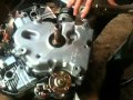
- Hydraulic Pump Mounting
- Place the engine key in the engine shaft keyway (it should fit tightly in the slot)
- Slide the larger end of the coupling on the engine shaft
- Tighten the lock screw with the appropriate hex key (ie: allen wrench).
- Bolt the hydraulic pump to the pump mounting plate using two (size) bolts and (size) nuts.
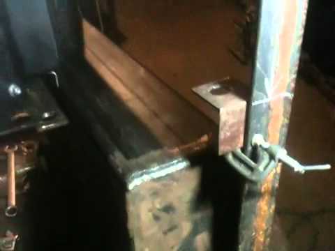
- Thread one nut on each of the four 3/4" x 4 1/2" bolts, insert the bolts through the holes on the hydraulic pump mounting plate as shown below.File:PumpBolts.jpg
- Verify that the key is in the hydraulic pump shaft, then align it with the keyway in the coupler and slide the pump upwards until the bolt heads touch the engine mounting plate as shown below. Tighten the lock screw on the coupling with the appropriate hex key.File:PumpPlateMounting.jpg
- Align the hydraulic mounting plate so its edges are parallel with the engine plate and weld the four 3/4" bolt heads to the engine plate as shown below.File:PumpPlateWelded.jpg
Battery mount
- Weld the two mounts to the angle iron and tank to form a rectangle for the battery as shown below.

- After the mount has cooled, lower the battery into the rectangle to verify it fits properly.
Quick Attach Plates
- Weld the [2] 3/8” x 4” x 27” plates to the top sides of the frame as shown. Secure at 45 degree angles before welding in place. Use solid, strong welds the entire length of the plates, as they will bear the load of the entire power cube.

Oil cooler and fan mounts
- Position the two ¼” x 2” x 22” plates to the outside of the frame, adjust so the oil cooler mounting bolts match the holes in the plates and is positioned as in the diagram below. Tack and weld the mounts in to the frame. Verify that the oil cooler bolts match the holes in the mounts.
- Use the mounting holes in the fan shroud and the oil cooler width for positioning the mounting plates as shown in the diagram below. Position the four ¼” x 2” x 1” plates, then tack and weld. Position the two ¼” x 2” x 24” plates against the 1” plates, then tack and weld. Place the fan on the supports and mark the mounts with bolt hole positions. Place the bolt heads against the fan mounting plate and weld in place. Verify that the bolts match the holes in the fan. Inside the frame, adjust the fan position to to position fan shroud ¼” from oil cooler fins. Be careful with radiator as the delicate fins are easily bent and damaged.
Keyswtich and Choke Brackets
- Clamp the keyswitch bracket to the frame as shown and weld in place.
- Clamp the choke bracket to the frame as shown and weld in place.
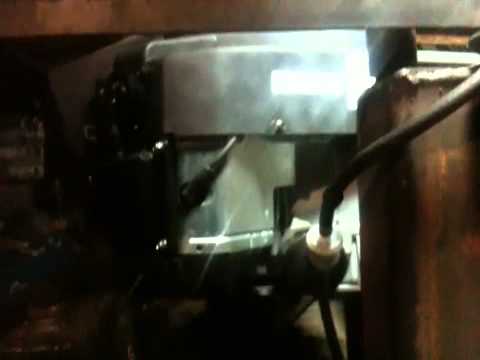
Solenoid Mounting Bolts
- Weld the solenoid mounting bolts to the hydraulic reservoir as shown below.
Finish and Painting
- Remove the engine if present
- Cover holes of tanks and any other place that should not be painted.
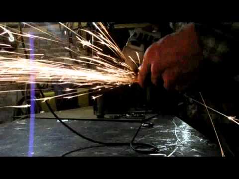
- Check all external surfaces for sharp edges and smooth with angle grinder.
- Remove any surface rust with wire brush and / or sandpaper.
- Apply a thorough coating of paint to all steel surfaces.
Install Solenoid
- Secure the solenoid on the bolts with two nuts.
Wiring
- The keyswitch has spade connectors for wiring and bolts to the frame for stability. These should be connected with matching crimp-on connectors.

- Connect the remaining wires, as in the diagram below:

- Note that the thicker lines represent the heavier wires that will carry high electrical current.
Keyswitch and Choke Installation
- Install the keyswitches in the brackets and wire as in the wiring illustration below.
- If your engine has a manual choke control, secure the choke control in its bracket.
Choke installation
- NOTE: Only necessary if your engine has a manual choke adjustment!
- Secure the engine choke knob as shown in the illustration below
Throttle Adjustment
- Use a wire to permanently set the throttle adjustment to full throttle as shown below

Final touches
- Install engine and secure with bolts, nuts and washers
- Connect wiring to key switch and solenoid
- Connect fuel line
- Connect coupling to engine shaft
- Install hydraulic pump on coupling and secure with nuts & washers
- Install fan and hydraulic oil cooler
See Also
See also Power_Cube_Fabrication_Procedure for older model.
Work in progress by Tom Griffing - File:Powercube.odt
Update Request from Tom
We're still not done with the Power Cube documentation - it still needs some updates:
- Once the next power cube is complete, take photo of the current model and replace old photos / images on these pages: Power_Cube, Power_Cube/Manufacturing_Instructions
- Key switches and choke
- Battery mount
- Painting: Procedures, BOM entries, tools
Previous Versions
Power Cube Fabrication June 2011