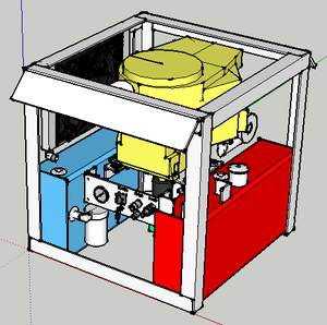
Power Cube 6/Manufacturing Instructions: Difference between revisions
No edit summary |
(→Steel Cut Sheet: was missing 2x 8" angle pieces, added descriptions) |
||
| Line 27: | Line 27: | ||
! Qty | ! Qty | ||
! Cut Length | ! Cut Length | ||
! Purpose | |||
|- | |- | ||
|Flat Steel | |Flat Steel | ||
| Line 32: | Line 33: | ||
|2 | |2 | ||
|1" | |1" | ||
|control panel mounting tabs | |||
|- | |||
|Angle Iron | |||
|1/4" x 2" x 2" | |||
|2 | |||
|8" | |||
|engine plate mounting tabs | |||
|- | |- | ||
|Angle Iron | |Angle Iron | ||
| Line 37: | Line 45: | ||
|2 | |2 | ||
|4" | |4" | ||
|pump attachment | |||
|- | |- | ||
|Angle Iron | |Angle Iron | ||
| Line 42: | Line 51: | ||
|1 | |1 | ||
|2" | |2" | ||
|gas line guard | |||
|- | |- | ||
|Angle Iron* | |Angle Iron* | ||
| Line 47: | Line 57: | ||
|10 | |10 | ||
|27" - 45 degree miter cuts (see diagram) | |27" - 45 degree miter cuts (see diagram) | ||
|main frame | |||
|- | |- | ||
|Tube - Rectangular | |Tube - Rectangular | ||
| Line 52: | Line 63: | ||
|2 | |2 | ||
|26" | |26" | ||
|tanks | |||
|- | |- | ||
|Flat Iron | |Flat Iron | ||
| Line 57: | Line 69: | ||
|1 | |1 | ||
|14" | |14" | ||
|control panel | |||
|- | |- | ||
|Flat Iron | |Flat Iron | ||
| Line 62: | Line 75: | ||
|2 | |2 | ||
|26" | |26" | ||
|attachment plate (powercube to lifetrac) | |||
|- | |- | ||
|Flat Iron | |Flat Iron | ||
| Line 67: | Line 81: | ||
|4 | |4 | ||
|12" | |12" | ||
|tank ends | |||
|- | |- | ||
|Flat Iron | |Flat Iron | ||
| Line 72: | Line 87: | ||
|1 | |1 | ||
|6" | |6" | ||
|pump mount | |||
|- | |- | ||
|Flat Iron | |Flat Iron | ||
| Line 77: | Line 93: | ||
|1 | |1 | ||
|13.5" | |13.5" | ||
|engine mount | |||
|- | |- | ||
|Expanded Steel | |Expanded Steel | ||
| Line 82: | Line 99: | ||
|1 | |1 | ||
|14" x 26" | |14" x 26" | ||
|radiator guard | |||
|} | |} | ||
Latest revision as of 19:58, 30 April 2014
| Power Cube 6 | ||
|---|---|---|
| Home | Research & Development | Bill of Materials | Manufacturing Instructions | User's Manual | User Reviews | File:Power Cube 6.png | |
| |||||||||||
Overview
This is the procedure for manufacturing version 6 of the OSE Power Cube.
Intro to Power Cube Construction Script
Preparation
Steel Cut Sheet
| Type | Cross Section | Qty | Cut Length | Purpose |
|---|---|---|---|---|
| Flat Steel | 1/8" x 4" | 2 | 1" | control panel mounting tabs |
| Angle Iron | 1/4" x 2" x 2" | 2 | 8" | engine plate mounting tabs |
| Angle Iron | 1/4" x 2" x 2" | 2 | 4" | pump attachment |
| Angle Iron | 1/4" x 2" x 2" | 1 | 2" | gas line guard |
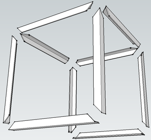
| Angle Iron* | 1/4" x 2" x 2" | 10 | 27" - 45 degree miter cuts (see diagram) | main frame |
| Tube - Rectangular | 1/4" x 6" x 12" | 2 | 26" | tanks |
| Flat Iron | 1/8" x 4" | 1 | 14" | control panel |
| Flat Iron | 3/8" x 4" | 2 | 26" | attachment plate (powercube to lifetrac) |
| Flat Iron | 1/4" X 6" | 4 | 12" | tank ends |
| Flat Iron | 1/4" X 6" | 1 | 6" | pump mount |
| Flat Iron | 1/4" x 8" | 1 | 13.5" | engine mount |
| Expanded Steel | 1/8" thick | 1 | 14" x 26" | radiator guard |
- Note: These angle iron pieces are to be cut at specific 45 degree angles for a mitered frame, as shown below.
Fabrication
Design Files
Sketchup
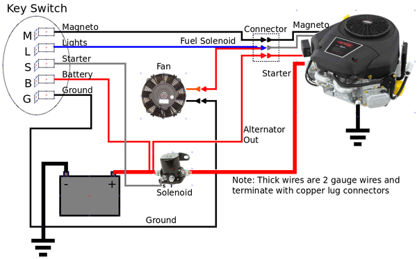
Electrical Diagram
From key switch:
Red - Battery Positive, Alternator Positive
Black - Battery Negative, Frame Ground
Yellow - Fuel Solenoid Positive, Fan Positive
Blue - Magneto Ground
White - Starter Solenoid Positive
Resolving Correct Labeling on Key Switch
Note: Convention on back of key switch. M and B have different label on the metal stud - I am assuming we go by the label imprinted in the plastic.
Jack's Small Engine says:
The letters on the back of an ignition switch stand for the following:
- M = Magneto
- S = Starter Solenoid
- L = Lights
- A = Accessory
- B = Battery
- G = Ground
- I = Ignition
- R = Regulator/Rectifier
Source: http://www.jackssmallengines.com/Products/TROY-BILT/ignition-switches-keys
As for the labeling on the switch itself, we can verity with an ohmmeter:
In OFF position, M should connect to ground. In ON position, M should not connect to anything
In OFF position, B should not connect to anything. In ON position, B should connect to L
Video
Subassembly Fabrication
The purpose of this section is to cut the raw steel into required lengths and shapes as required for final assembly. These step includes drilling and cutting steel up to 1/4” in thickness.
Assembly
Power Cube assembly requires all the parts listed in the Bill Of Materials to be available and prepared as detailed in the “Fabrication” section (above). Assembly requires a welder (electric or torch) capable of welding metal 3/8” thick.
A "Stronghand" clamp has proven useful for 90 degree alignment of the frame members
- File:Frameweld.jpgPower Cube Frame welding
- Frame
- Gas tank
- Hydraulic tank
- Engine and Hydraulic Pump Mounts
- Battery mount
- Oil cooler and fan mounts
- Solenoid Mounting Bolts
- Throttle mount
- Keyswitch mount
- Quick Attach Plates
- Painting
- Install Hydraulic Components
- Install Engine and Pump
- Install Solenoid
- Install Muffler
- Wiring
- Install Throttle Control
Final touches
- Install engine and secure with bolts, nuts and washers
- Connect wiring to key switch and solenoid
- Connect fuel line
- Connect coupling to engine shaft
- Install hydraulic pump on coupling and secure with nuts & washers
- Install fan and hydraulic oil cooler
See Also
See also Power_Cube_Fabrication_Procedure for older model.
Work in progress by Tom Griffing - File:Powercube.odtFile:Powercube.pdf
Previous Versions
Power Cube Fabrication June 2011
Peer Review
- I would do double chain coupler. I have had good experience with it - it will extend pump life because it will eliinate any strain on the pump shaft, while easing accuracy requirements for pump mount welding.


