Microtractor/Research Development: Difference between revisions
| Line 68: | Line 68: | ||
'''Changes from first proposal:''' | '''Changes from first proposal:''' | ||
Shortened quick connect wheel module to one "cell." | Shortened quick connect wheel module to one "cell." Need help figuring out how the shaft and bearings will fit into this. Tractor width (outer rim to rim) decreased from 62" to 46" | ||
Tweaked frame proportions | Tweaked frame proportions and design | ||
Straight loader arms (Thanks [[Dorkmo]] for uploading the bent arms, QA plate, and quick connect wheels on 3d warehouse) | Straight loader arms (Thanks [[Dorkmo]] for uploading the bent arms, QA plate, and quick connect wheels on 3d warehouse) | ||
| Line 79: | Line 79: | ||
Add hinged or removable control panel behind power cube plus hydraulic mounts. | Add hinged or removable control panel behind power cube plus hydraulic mounts. | ||
Short shafts and bearings for QC wheels | |||
=Industry Standards= | =Industry Standards= | ||
Revision as of 21:14, 14 June 2012
| Microtractor | ||
|---|---|---|
| Home | Research & Development | Bill of Materials | Manufacturing Instructions | User's Manual | User Reviews | 
| |
Status
- See Status Briefs
- Andrew Spina is proposing an OSE Spec version for modularity, a sound approach - [1]
Prototype 1
Design
- Same frame concept as Tractor except with 18 hp recommended
- Wheel motors are staggered to allow for a more narrow frame
- Identical frame desing as Tractor allows one to build a microtractor readily based on the Tractor
- Parts interchangeability between Tractor and Bulldozer
Prototype II Proposals
Main > Food and Agriculture > Farm equipment > MicroTrac
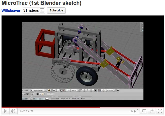
Prototype II - Will Cleaver
MicroTrac Prototype uses a Power Cube just like MicroTrac Prototype I, but it uses more of the LifeTrac design pattern language: a cubic, bolt-together, 4x4x1/4" tubing construction, with wheel shaft mounting plates.
See the video:
Design Repository: http://openpario.mime.oregonstate.edu/documents/722
Comments and Questions on v0.1
- How do we interpret dimensions on v0.1 in the Blender file? Please comment. What are the basic size dimensions for the wheel base?
- Reduce loader arm length and make it more vertical in v0.11. It's sticking too far out.
- I think the bearings have to be on opposite sides, as 4" separation is too small, leading to large stress on motor shaft
- Please render MicroTrac and LifeTrac next to each other for size comparison:
- What is the max height reach of bommon of loader quick-attach plate?
For practical reasons, it would be useful to design MicroTrac with sufficient reach to load the CEB press. The present design is more like MiniTrac, not MicroTrac.
Can you also design a MicroTrac: but a platform under the power Cube, put on 4 wheels with tracks, but 2 drive motors, and a loader attached to the Power Cube? It would have low reach, only like 2-3 feet - but would be a true MicroTrac.
Prototype Proposal - Andrew Spina
Prototype Proposal - Graham Robertson
[Download second drawing, and picture of first iteration] (still in the works, improved upon first design). This is a crude, unfinished representation, long way to go before its a true fab drawing.
I would like to hear ideas, suggestions or help drawing up:
a control panel behind the power cube, that can be easily removed to allow for removal of the power cube.
I like the idea of tank treads, as we could really downsize the width of the frame. Not sure about the technical part of designing this.
Changes from first proposal:
Shortened quick connect wheel module to one "cell." Need help figuring out how the shaft and bearings will fit into this. Tractor width (outer rim to rim) decreased from 62" to 46"
Tweaked frame proportions and design
Straight loader arms (Thanks Dorkmo for uploading the bent arms, QA plate, and quick connect wheels on 3d warehouse)
Next iteration:
Tank treads?
Add hinged or removable control panel behind power cube plus hydraulic mounts. Short shafts and bearings for QC wheels
Industry Standards
See Also
