D3D Universal

We are now producing kits and finished machines - see https://www.opensourceecology.org/d3d-universal-2/
Product
CAD
![]() Hint: Wire loom holder on z is missing
Hint: Wire loom holder on z is missing
3D Printer


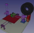
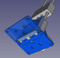
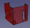
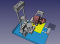
![D3D Universal Rework - [1]. Newer - File:D3D Universal Assy.fcstd. Note: sensor holder is old fine in assemly; Extruder separate file for sensor holder is correct.](/images/thumb/9/9a/D3D-Universal-Axis-2019.12.14.png/120px-D3D-Universal-Axis-2019.12.14.png)
D3D Universal Rework - [1]. Newer - File:D3D Universal Assy.fcstd. Note: sensor holder is old fine in assemly; Extruder separate file for sensor holder is correct.
D3D Universal - scaled to 12" print bed - FreeCAD - File:D3du12inchscaled.fcstd
D3D Universal Rework X Axis - File:D3D Universal X Axis.fcstd
D3D Universal Rework Y Axis - File:D3D Universal Y Axis.fcstd
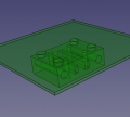
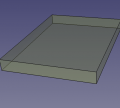
D3D Universal Print Bed - File:D3D Universal Print Bed.fcstd
D3D Universal Rework Z Axis - File:D3D Universal Z Axis.fcstd
D3D Universal Rework Base - File:D3D Universal Base.fcstd
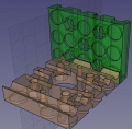
Spool holder assembly- File:Spoolholdersassy.fcstd
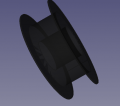
Spool- File:Filamentspool.fcstd
D3D Universal Rework Controller - File:D3D Universal Controller.fcstd
D3D Universal Rework Spool Holder - FreeCAD - File:D3D Universal Spool Holder.fcstd. STL - File:D3D Universal Spool Holder.stl
Spool holder rod . FreeCAD - File:Spoolholderrod.fcstd. STL - File:Spoolholderrod.stl
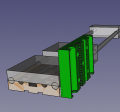
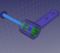
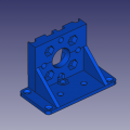
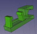
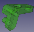
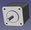
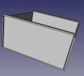
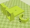
![[10] Motor Side of Axis - 221k - FreeCAD -File:Universal axis motor side.fcstd. STL - File:Universal axis motor side.stl](/images/thumb/4/45/Motorside.jpg/120px-Motorside.jpg)
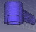
 [10] Motor Side of Axis - 221k - FreeCAD -File:Universal axis motor side.fcstd. STL - File:Universal axis motor side.stl
Universal axis carriage: File:Universal axis carriage side.fcstd. STL - File:Universal axis carriage side.stl
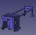
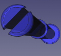
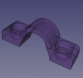
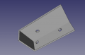
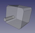
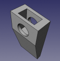
![[10] Short Idler Side - 75k - FreeCAD - File:Universal Axis Idler Side short version.fcstd. STL - File:Universal Axis Idler Side short version.stl.](/images/thumb/a/ae/Idlershort.jpg/120px-Idlershort.jpg) [10] Short Idler Side - 75k - FreeCAD - File:Universal Axis Idler Side short version.fcstd. STL - File:Universal Axis Idler Side short version.stl.
[10] Short Idler Side - 75k - FreeCAD - File:Universal Axis Idler Side short version.fcstd. STL - File:Universal Axis Idler Side short version.stl.
Carriage to side motor piece- FreeCAD - File:Carriagetosidemotor.fcstd. STL - File:Carriagetosidemotor.stl.
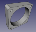
D3DS motor piece with bracket for x and z-axis
FreeCAD file -File:D3DS motor bracket.fcstd
STL file -File:D3DS motor bracket.stl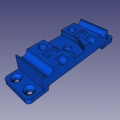
D3DS idler side piece for Y-axis
FreeCAD file -File:D3DS idler screwdown.fcstd
STL file -File:D3DS idler screwdown.stl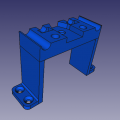
D3DS elevated idler side piece for Y-axis
FreeCAD file -File:D3DS idler high screwdown.fcstd
STL file -File:D3DS idler high screwdown.stl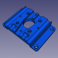
D3DS motor side piece for Y-axis
FreeCAD file -File:D3DS motor side screwdown.fcstd
STL file -File:D3DS motor side screwdown.stl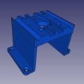
D3DS elevated motor side piece for Y-axis
FreeCAD file -File:D3DS motor side high screwdown.fcstd
STL file -File:D3DS motor side high screwdown.stl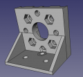
Mount of Z motor to base plate. File:D3DS motor bracket x axis.fcstd. STL - File:D3DS motor bracket x axis.stl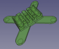
3D Printed Bed Holder File:Newbed.fcstd. STL - File:Newbed.stl
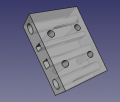
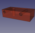
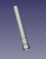
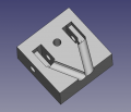
![[10] Belt Holding Peg - FreeCAD original size - File:Peg 8mm rods.fcstd. STL at 85% size, works well - File:Peg 8mm rods.stl](/images/thumb/a/a5/Peg85.jpg/120px-Peg85.jpg) [10] Belt Holding Peg - FreeCAD original size - File:Peg 8mm rods.fcstd. STL at 85% size, works well - File:Peg 8mm rods.stl
[10] Belt Holding Peg - FreeCAD original size - File:Peg 8mm rods.fcstd. STL at 85% size, works well - File:Peg 8mm rods.stl
'Cable clip for end of axis nut catch. - FreeCAD - File:Cableclip2.fcstd. STL - File:Cableclip2.stl
Endstop holder. - File:Endstopholder2.fcstd. File:Endstopholder2.stl. See Open Source Endstop Holder
![D3D Universal Rework - [1]. Newer - File:D3D Universal Assy.fcstd. Note: sensor holder is old fine in assemly; Extruder separate file for sensor holder is correct.](/wiki/File:D3D-Universal-Axis-2019.12.14.png)
![[10] Motor Side of Axis - 221k - FreeCAD -File:Universal axis motor side.fcstd. STL - File:Universal axis motor side.stl](/wiki/File:Motorside.jpg)

![[10] Short Idler Side - 75k - FreeCAD - File:Universal Axis Idler Side short version.fcstd. STL - File:Universal Axis Idler Side short version.stl.](/wiki/File:Idlershort.jpg)
![[10] Belt Holding Peg - FreeCAD original size - File:Peg 8mm rods.fcstd. STL at 85% size, works well - File:Peg 8mm rods.stl](/wiki/File:Peg85.jpg)
Printer Extruder
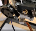
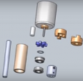
![]() Hint: Note the small extruder gear shown is MK8- we are using an MK7. Note: Supervolcano nozzle has heat transfer issues, so we are using a 3 mm E3D v6 heat break with success (6mm threads on both sides - note that E3D v6 has 6 mm on the nozzle side, 7 mm on the cold side. Can also test Titan Aero v6 1.75 mm - which appears to have 6 mm thread on both sides. 3mm titan aero is definitely 6 mm thread on each side: see E3D_Titan_Aero_Extruder#CAD
Hint: Note the small extruder gear shown is MK8- we are using an MK7. Note: Supervolcano nozzle has heat transfer issues, so we are using a 3 mm E3D v6 heat break with success (6mm threads on both sides - note that E3D v6 has 6 mm on the nozzle side, 7 mm on the cold side. Can also test Titan Aero v6 1.75 mm - which appears to have 6 mm thread on both sides. 3mm titan aero is definitely 6 mm thread on each side: see E3D_Titan_Aero_Extruder#CAD
Notes: Still missing from final assembly by MJ: fan, heat sink heat exchanger, MK7 gear, spring. In final CAD of extruder assy, heat break does not stick out of the heat sink. In reality, it sticks out about 3 mm. Where is the discrepancy if the heat break is 25 mm long?


![Simple Extruder WIP. Github - [2]. Gitlab - [https://gitlab.com/marcin_ose/d3d-universal.](/images/thumb/5/59/CC_simple_extruder_dev_03NOV2019.png/120px-CC_simple_extruder_dev_03NOV2019.png)
Simple Extruder WIP. Github - [2]. Gitlab - [https://gitlab.com/marcin_ose/d3d-universal.
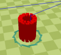
![Extruder Spring for Simple Extruder. Buy + spec - [3]. FreeCAD file - File:Extruderspring.fcstd](/images/thumb/7/79/Extruderspring.png/120px-Extruderspring.png)
Extruder Spring for Simple Extruder. Buy + spec - [3]. FreeCAD file - File:Extruderspring.fcstd
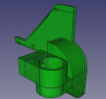
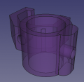
![Extruder assembly - Gitlab - [4]. FreeCAD - File:Simpleextruderassy.fcstd](/images/thumb/2/2b/Finalextruder.png/120px-Finalextruder.png)
Extruder assembly - Gitlab - [4]. FreeCAD - File:Simpleextruderassy.fcstd
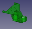
![Main extruder part. - Gitlab - [5]. FreeCAD - File:Mainextruderpart.fcstd. STL - File:Extruder main.stl](/images/thumb/c/c8/Mainextruderpart.png/120px-Mainextruderpart.png)
Main extruder part. - Gitlab - [5]. FreeCAD - File:Mainextruderpart.fcstd. STL - File:Extruder main.stl
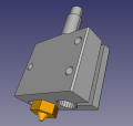
Extruder Active Cooling and Sensor Mount File:ExtruderActiveCoolingAndSensor.FCStd. STL - sensor holder - File:SensholderSimple.stl
Extruder Active Cooling with Sensor Mount + Plotter Mount File:ExtrCoolSensPlt.fcstd. STL - Cooling/Sensor/Plotter Mount - File:ExtrCoolSensPlt.stl
Spring tensioner -File:SpringTensioner.FCStd. STL - File:Tensioner.stl
Jig to cut the heat sink -File:HeaterSinkJig.FCStd
heat sink -File:HeatSink.FCStd. Technical drawing - File:Heatsinktechdraw.FCSTD
Spiral linear bearing - parametric, but parameters set up for D3D -File:SpiralLinearBearing.zip
Volcano heater block. File:Volcanoheaterblock.fcstd.
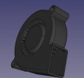
File:5015blower.fcstd 5015 Blower - positionally correct for D3D Universal.
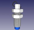
8 mm sensor. Download - File:8mmsensor.fcstd
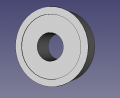
608 skateboard 8x22x7 mm Bearing. Download - File:608Bearing.FCStd
40x10mm fan File:40x10fan.fcstd
Stepper MotorFile:Steppermotor.fcstd
Stepper Motor from FaceplateFile:Nema17face.fcstd
Super Volcano NozzleFile:SuperVolcanoNozzle.fcstd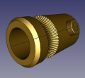
Drive GearFile:Drivegear.fcstd
![3 mm heat break.File:3heatbreak.fcstd. Re-Source - [6]](/images/thumb/5/5c/3heatbreak.png/120px-3heatbreak.png)
3 mm heat break.File:3heatbreak.fcstd. Re-Source - [6]
4040 heatsink.File:Heatsink.fcstd
![Simple Extruder WIP. Github - [2]. Gitlab - [https://gitlab.com/marcin_ose/d3d-universal.](/wiki/File:CC_simple_extruder_dev_03NOV2019.png)


Control Panel
See more at 3D Printer Control Panel


Control Panel - FreeCAD -File:Controlpanel v1904.fcstd. Bent panel STL - File:Bentpanel v1904.stl
D3D v19.04 Power Supply - FreeCAD -File:Powersupply v1904.fcstd
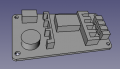
![RAMPS 1.4 - FreeCAD -File:RAMPS14 v1904.fcstd. Full detailed file - 4MB - [7]](/images/thumb/a/a5/RAMPS14_v1904.png/120px-RAMPS14_v1904.png)
RAMPS 1.4 - FreeCAD -File:RAMPS14 v1904.fcstd. Full detailed file - 4MB - [7]
![Stepper driver - FreeCAD -File:Stepperdriver v1904.fcstd. File for detailed LCD controller and endstop can be found at [8]](/images/thumb/a/a8/Stepperdriver_v1904.png/120px-Stepperdriver_v1904.png)
Stepper driver - FreeCAD -File:Stepperdriver v1904.fcstd. File for detailed LCD controller and endstop can be found at [8]
![Solid state relay - FreeCAD -File:Ssr v1904.fcstd. Source: [9]. See Fotek SSR. Dimensions verified with Amazon source.](/images/thumb/b/ba/Ssr_v1904.png/120px-Ssr_v1904.png)
Solid state relay - FreeCAD -File:Ssr v1904.fcstd. Source: [9]. See Fotek SSR. Dimensions verified with Amazon source.
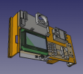
![Reprap Discount Smart Controller - FreeCAD -File:Smartcontroller v1904.fcstd. Source: [10].](/images/thumb/f/fe/Smartcontroller_v1904.png/120px-Smartcontroller_v1904.png)
Reprap Discount Smart Controller - FreeCAD -File:Smartcontroller v1904.fcstd. Source: [10].
![Ground Fault Connection Interrupt (GFCI) outlet - FreeCAD -File:Gfci v1904.fcstd. CAD source at McMaster Carr: [11]. May not represent actual GFCI.](/images/thumb/5/50/Gfci_v1904.png/117px-Gfci_v1904.png)
Ground Fault Connection Interrupt (GFCI) outlet - FreeCAD -File:Gfci v1904.fcstd. CAD source at McMaster Carr: [11]. May not represent actual GFCI.
Wire box cover. - FreeCAD -File:Wireboxcover v1904.fcstd.
Power cord wire clamp - FreeCAD -File:Heatbed wirelock.fcstd.
Inner part of D3D Electric Plug - FreeCAD File:D3DPlugInner.fcstd. STL - File:D3DPlugInner.stl
Outer cover of D3D Electric Plug - FreeCAD File:D3DPlugCover.fcstd. STL file is scaled to 105% already - File:D3DPlugCover.stl
Plotter
![]() Hint: Amazing, works out of box. Improvements: raise tip next to carriage. Double-sided attachment. Probe on right, not left, to optimize print area
Hint: Amazing, works out of box. Improvements: raise tip next to carriage. Double-sided attachment. Probe on right, not left, to optimize print area


![D3D Universal with 3D printer motor functioning as a CNC mill. - FreeCAD -[12] or Michel's repo.](/images/thumb/6/6e/D3duniversalmill.png/120px-D3duniversalmill.png)
D3D Universal with 3D printer motor functioning as a CNC mill. - FreeCAD -[12] or Michel's repo.
D3D Simple Working Copy by Marcin - FreeCAD -File:D3Dsimple.fcstd
![D3D Universal with plotter attachment. - See D3D Universal Plotter by Ferdi Meier. Gitlab - [13]](/images/thumb/8/88/D3Duniversalplotter1.jpg/120px-D3Duniversalplotter1.jpg)
D3D Universal with plotter attachment. - See D3D Universal Plotter by Ferdi Meier. Gitlab - [13]
Plotter Pen Attachment. - File:Plotterpen.fcstd. Start from Ferdi Log, adaptation by Marcin Log. STL printed - File:Plotterpen.stl.
Simple extruder for 1.75 mm filament. - By London International Academy team. From Simple Extruder.
Pen holder clamp for plotter - includes sensor holder - File:Penholderclamp.fcstd. STL - File:Penholderclamp.stl
Mill


Simple spindle - By John Stager team. See Simple Spindle.
Arduino Uno for motor power supply. See Emmanuel Log.
3D by Yale
Technical Drawing Library
Useful technical drawings for fabricating parts:
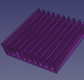
- File:Heatsinktechdraw.FCSTD - heat sink dimensional drawing
Diagram
BOM
Working Doc
Includes Review and Data Collection
| Description | Link to Work Product | % | |
|---|---|---|---|
| DESIGN | |||
| 1 | Requirements + Value Proposition | [[{{{0}}} Requirements + Value Proposition]] | {{{1}}} |
| 2 | Industry_Standards | [[{{{0}}} Industry Standards]] | 50 |
| 3 | Conceptual Design | [[{{{0}}} Conceptual Design]] | {{{3}}} |
| 4 | Module Breakdown | [[{{{0}}} Module Breakdown]] | {{{4}}} |
| 5 | 3D CAD | [[{{{0}}} 3D CAD]] | {{{5}}} |
| 6 | Calculations | [[{{{0}}} Calculations]] | {{{6}}} |
| 7 | Electronics Design | [[{{{0}}} Electronics Design]] | {{{7}}} |
| 8 | Wiring and Plumbing | [[{{{0}}} Wiring and Plumbing]] | {{{8}}} |
| 9 | Software | [[{{{0}}} Software]] | {{{9}}} |
| BILL OF MATERIALS | |||
| 10 | BOM | [[{{{0}}} BOM]] | 50 |
| 11 | vBOM | [[{{{0}}} vBOM]] | {{{11}}} |
| 12 | CAM Files | [[{{{0}}} CAM Files]] | {{{12}}} |
| 13 | Cut List | [[{{{0}}} Cut List]] | {{{13}}} |
| BUILD | |||
| 14 | Build Instructions | [[{{{0}}} Build Instructions]] | 20 |
| 15 | Fabrication Drawings | [[{{{0}}} Fabrication Drawings]] | {{{15}}} |
| 16 | Exploded Part Diagram | [[{{{0}}} Exploded Part Diagram]] | {{{16}}} |
| 17 | Production Engineering | [[{{{0}}} Production Engineering]] | {{{17}}} |
| DATA COLLECTION | |||
| 18 | Build Pictures and Video | [[{{{0}}} Build Pictures and Video]] | {{{18}}} |
| 19 | Data Collection | [[{{{0}}} Data Collection]] | {{{19}}} |
| 20 | Future Work | [[{{{0}}} Future Work]] | {{{20}}} |
Build
Cut List
- [6] 8 mm rods, 12" each
- [1] 8 mm rod, 3D printed,
- [1] 2x12 lumber, 12.5" long
- [3] belts, 26" long
D3D Universal Axis
Platform on stilts so extruder reaches bed:
Nozzle does not reach bed:
Extruder Build
Plotter Build
Design Concepts
Plotter
embedded my website on wiki https://feadi.github.io/OSE/.
Played with gtlf-viewer
Wiring
Software
- Printer - Marlin, Lulzbot Cura, OSE Linux, FeF Microfactory printer profiles
Plotter File Generation
- Plotter - Using Inkscape to Generate Gcode
Code
Firmware
- Marlin - File:Marlin Universal.zip
Production Engineering
D3D Universal Production Engineering
Product
See D3D Universal Product Page.