Ironworker/Research Development: Difference between revisions
| Line 98: | Line 98: | ||
==See Also== | ==See Also== | ||
*[[Hole Puncher Die]] | *[[Hole Puncher Die]] | ||
*[[Hole Puncher Calculations]] | |||
*[[120 Ton Hole Puncher]] | *[[120 Ton Hole Puncher]] | ||
*[http://blog.opensourceecology.org/2010/07/open-source-150-ton-hole-puncher/ Blog Announcement] | *[http://blog.opensourceecology.org/2010/07/open-source-150-ton-hole-puncher/ Blog Announcement] | ||
=Calculations= | =Calculations= | ||
Revision as of 16:08, 29 September 2011
| Ironworker | ||
|---|---|---|
| Home | Research & Development | Bill of Materials | Manufacturing Instructions | User's Manual | User Reviews | 
| |
Overview
We are currently in the design stages of the shear prototype. There's quite a few things we need to know before the design can continue. Please answer any of the following questions if you can:
- What is the necessary force to shear 1" thick x 12" wide metal?
Concepts
- 120 ton for up to 1.5" holes in 1" metal
- Can be based on the existing Holepuncher Prototype I design
- Shear for 8-12" of 1" steel
- Angle cutter for up to 6x6 angle
- DIY shear blade - made from hardening of mild steel, at $40 in materials
- May involve Induction Furnace for hardening
From SMJ Tsakok
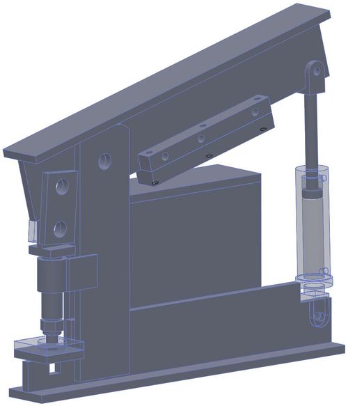
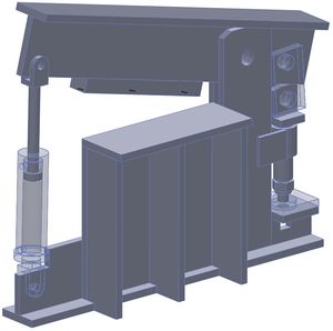
Adding a metal shear element to Ironworker Prototype I:
Solidworks model:
File:Holepunhersolidwks.tar.gz
Research
Other Research
Small (<50 ton) ironworker from Northern Tool:
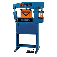
- http://www.docstoc.com/docs/16819551/The-Marvels-of-Hydraulic-Ironworker-Bending-Machine-and-Punching-Machine
- http://www.articlelarder.co.cc/?p=292
- this has the original article by Issac Wang
The Marvels of Hydraulic Ironworker, Bending Machine and Punching Machine
Ironworker machines can shear, punch holes and notch In steel plates. These machines generate force using hydraulic systems or mechanical leverage. Modern systems make use of hydraulic rams that are powered by heavy alternating current electric motors.
Incidentally, the hydraulic ironworker is an engineering marvel. It is not to be mistaken for a single machine. It is the amalgamation of 5 machines clubbed into a single engineering wonder. It comprises of a punching machine, a plate shear, a section shear, a punch and shear machine and a coper-notcher.
Irrespective of the size of any fabricator’s workshop, an ironworker forms the backbone. It is a versatile machine. It is an important tool in a metal workers shop. Very often, a cheap hydraulic ironworker is constructed. This leads to erosion of the die and the punch on the front rims. Higher quality machines are a must because they ensure durability and productivity. It ensures tooling longevity and helps you capitalize on the machine's total tonnage.
Selecting a right hydraulic ironworker from an OEM/ODM manufacturer for your application can be taxing job. There are some key pointers like versatility and safety features that you need to keep In mind. Consider its quality and capacity as well. The material thickness is another important aspect to be considered. It indicates whether you should use a trim press or an ironworker. An ironworker is capable of punching plate up to 1 inch. Usually, trim presses are used on sheet material 1/4 in. and thinner. ironworker machines are opted for shorter production runs and those applications for which tolerances are not too critical.
Ironworker machines are usually rated by tonnage at the punch station. it is essential to ascertain the maximum material thickness so that you can establish the tonnage range required for your punching application. You need to also examine the product and the steel rack that you need to fabricate. Make sure you determine the maximum hole diameter that needs to be punched. Don’t forget to focus on the maximum width and thickness of the angle, channel and rod to be bent or sheared.
You can also look out for a bending machine and options like larger press brake bending attachments. These machines are capable of using a larger variety of tooling as compared to those with built-in stations, however, you need time to switch from one operation to the other.
when choosing an ironworker from an OEM_ODM manufacturer or exporter, 'safety' should be your top most concern. Addressing safety issues is extremely Important. While there are many OEM/ODM manufacturers in the business, especially In Taiwan, you an make sure that you select the hydraulic ironworker and bending machine that meets ANSI B 11-5 standards.
It is necessary no examine the guarding as well. Make sure it is adjustable and it complies with the ANSI standard. Be careful of hydraulic ironworker and punching machine with automatic urethane hold-downs The Blade is dangerous and it can hurt you in the process. ‘Adjustable Stroke Control’ another feature to look out for. This ensures safety as well as productivity. It minimizes machine movements and reduces the number of pinch points. It also increases your productions and strokes per minute. It is a crucial factor in bending and special tool applications. The upstroke and downstroke need to be adjusted.
Thanks to ironworkers, punching holes of different sizes and shapes has never been so easy. From cutting to notching, from shearing to bending bars, you can do it all!
Examples
http://www.edwardsironworkers.com/60ton.html
Hole Punch Dies (see [Hole Punch Dies])
Companies
- Edwards - [3]
- Cleveland Punch and Die - [4]
- Metalpro - cheap ironworkers - http://www.metalprocorp.com/viewProduct.jsp?id=24
- Fabtec - metal workers and parts - [5]
Standard Metal Punch Units
- Complete unit? [6] Yes, but only sheet metal.
Hand Punch
Parts
Operating Tips
Metal Punch Fabrication Strategy
Using s punch stem and coupling nut [13], combined with a punch and die standard [14] - we are ready to put together a metal punching assembly, provided that
See Also
Calculations
Force Required to Shear the metal
Using the shear tonnage calculator at Multicyl, the force required to shear 80KSI Tensile strength A36 Steel is:
- 1"x12"=480 Tons
- 1"x10"=400 Tons
On Cut Smart's website, the formula to calculate the required pounds of force to shear any material is: "Straight from the from Machinery's Handbook 25th ED. P1924 “P = periphery x thickness x tensile strength(PSI) where P is cutting force in pounds.”
So, using the periphery(the length of the cut) as 12", the thickness as 1", and the tensile strength as 80,000 PSI (common upper end value for A36 steel), we get, P=12"x1"x80,000PSI= 960,000 pounds = 480 tons
- Given that the two websites match, as well as a few others I could find, this calculation is valid. The question is, how do we generate such high tonnage? Do we really want to make the machine that powerful?
- Likewise, we can calculate the required tonnage to cut the 6"x6"x1/2" angle:
P=12"x1/2"x80,000PSI= 480,000 pounds= 240 tons
- Alternately, If 6x6 is too hard to cut, we could cut 4"x4"x1/2"
P=8"x1/2"x80,000PSI= 320,000 pounds= 160 tons
- Shear Angle - is the angle from the horizontal with which a cutting blade contacts the workpiece. The above calculations assume a shear angle of zero degrees. With a shear angle of just 5 degrees from the horizontal, the ironworker needs significantly less force to shear the aforementioned steel.
- Angle Calculation Note - The force calculation for angles should yield significantly lower values due to the support piece for the angle (the angle is cut with the two edges at the top, the cross-section area being sheared has no support from the rest of the angle, hence requires much less force than calculated above).
The required moment to act on blade
To find this, we must make a few basic assumptions:
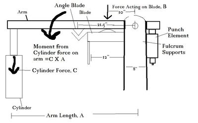
- The fulcrum supports are 8" wide
- The blade is 12" wide and placed as close as possible to the fulcrum supports.
- The force will be applied at the center of the blade and distributed evenly.
- The required moment will be whichever is highest for a particular design, the blade force, or the angle shear force.
- In design 1, the angle shear is between the blade and the cylinder
- In design 2, the angle shear is between the cylinder and the fulcrum supports.
- As the distance of the blade to the fulcrum doesn't change, the blade moment is the same for design 1 and design 2.
Blade moment
Since the force on the blade(B) is known, as is its distance from the fulcrum, we can calculate the necessary moment, M. M=Force(B) x Distance from the pivot(d) (10")
For the capability of cutting 1"x12", B=480 tons.
- M=480 tons x 10" = 4800 inch tons
For the capability of cutting 1"x10", B=400 tons.
- M=400 tons x 10" = 4000 inch tons
Angle Shear moment
B=240 tons
Design 1, 6x6 angle: d=21.5"
- M=240 tons x 21.5" = 5160 inch tons
Design 1, 4x4 angle:
- M=160 tons x 21.5" = 3440 inch tons.
Design 2: d= 9"
- M=240 tons x 9" = 2160 inch tons
Required Moments
Design 1, 6x6: As the angle moment is the highest, this value is the requirement, or M=5160 inch tons. This means this machine would have the capacity for 1"x12" flat cuts.
Design 1, 4x4: The blade moment is highest, so for the 12" cut, M=4800 inch tons. For the 10" cut, M=4000 inch tons.
Design 2: The Blade moment is highest, so for the 12" cut, M=4800 inch tons. For the 10" cut, M=4000 inch tons.
Calculating the arm length and cylinder size
There are two possible designs for this; the blade being between the cylinder and the fulcrum supports(Design 1), or the blade being on the other side, along with the punch (Design 2)
- If building an ironworker whose max cutting ability is under 1" x 10", you could scale the cylinder size down according to your desires.
Since the such high force is required to shear the desired metal, we will use the largest available cylinder with an 8" stroke available at surplus center.
To calculate the arm length using this cylinder, we must set the cylinder force (C) multiplied by the lever arm (A) equal to the required moment (M), so A X C = M. Solving for A, we get A=M/C
Design 1
In this particular design, the cylinder will be contracting while shearing, which means the cylinder tonnage we are using must be on the contracting side. See Cylinder Tonnage Calculations for how to find the contracting strength. The calculated contracting tonnage (C) for this specific cylinder is 56.52 tons.
6x6 M=5160 inch tons, so A=5160 inch tons / 56.52 tons = 91.30 inches.
4x4, 12" M=4800 inch tons, so A=4800 inch tons / 56.52 tons = 84.93"
4x4, 10" M=4000 inch tons, so A=4000 inch tons / 56.52 tons = 70.77""
Design 2
In this design, the cylinder is expanding while shearing the 1"x12", so we use the expanding cylinder tonnage for the 8" bore cylinder, or 75.36 tons.
A=M/C For the capability of cutting 1"x12", M=4800 Inch tons.
- A=4800 inch tons/ 75.36 tons = 63.69 inches
For the capability of cutting 1"x10", M= 4000 inch tons
- A=4000 inch tons / 75.36 tons = 53.08 inches
We should also double check to make sure the punch still has enough power We must find the required punch moment, and insure it is less than the required blade moment.
- M= Punch force (P) x distance (d). P= 150 tons, d=23"
M= 150 tons x 23" = 3450 inch tons. This is less than the blade moment, so we are OK.
Design analysis
As we can see, both designs are going to require really long overall arms. Here are the calculated lengths:
Design 1 will require A+6", including the end amounts (this depends on how close the cylinder attaches to the end, and how far the punch is away from the end).
- 6x6= 91.3"+6" = 97.3 inches
- 4x4, 12"= 84.9"+6" = 90.9" including the end amounts.
- 4x4, 10"= 70.7"+6" = 76.7", including the end amounts.
Design 2 will require A+23", including the end amounts.
- For 12": 63.36+23"= 96.36", including the end amounts.
- For 10": 53.08+23"= 66.08", including the end amounts.
Calculation of the size of the pin
To find the size of the pin, we must first find how much force is acting on it when it is most stressed. In this case, it is when we are cutting thru the 1"x10" metal.
Since the arm is not accelerating upwards, we can do a statics calculation, and assume the sum of all the forces is zero. So: -31.5T+400T+P=0 Solving for P, we get P=368.5T.
Now, we must use this to find the necessary cross sectional area of the pin to prevent it from warping.
- At each side, where the pin goes thru the pin holders, a force of P/2 is applied to it via the fulcrum supports. This means that there is a shear force of P/2, or 184.25T acting on the pin.
- The allowable shear for A36 steel is 7.2TSI.
- To calculate the radius of the pin, we must set the product of the cross sectional area (A) and the allowawble shear (S) equal to the shear force (P/2). or, AxS=P/2
- We can replace A with PixR^2, since the cross sectional area is a circle. So PixR^2xS=P/2. Solving for R, we get R=Root[(P/2)/Pi/S]
- Plugging it all in, we get R=Root[184.25T/3.14/7.2TSI]=2.86"
- To find the diameter of the pin, we simply multiply Rx2. so D=5.71
Now that's a big pin!
