Well-Drilling Rig/Research Development
| Well-Drilling Rig | ||
|---|---|---|
| Home | Research & Development | Bill of Materials | Manufacturing Instructions | User's Manual | User Reviews | 
| |
Design Goals
what goals should we have for the rig?
should it be an old fashioned wooden derrick?
- errected on site
- wood could be used for something else later
- for drilling one hole for a single community (worktime/price per hole come high!)
reusable and on wheels?
- drill multiple holes quickly and easily
- metal? more expensive?
- lifetrac additional tool, so only need drill & feed mechanisim & additional length drill strings?
- 2nd drill head to change Liftrac full cave/mine making machine?
- Software for automate Lifetrac to drill hole groups? (like for blasting construction stones?)
how deep should it drill? geothermal or just water?
- 200m (600') is typical for geothermal, for water 100m is usually enough. Basically deeper only needs larger drill strings reservour.
Well - Current Work
Water/Mud Swivel
link to some basic ideas about a swivel google doc
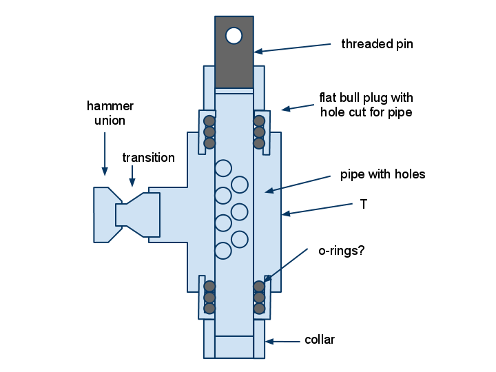
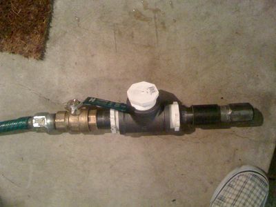
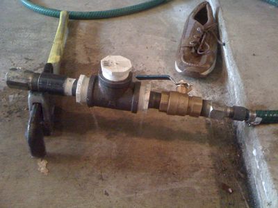
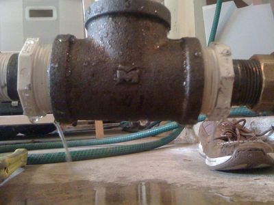
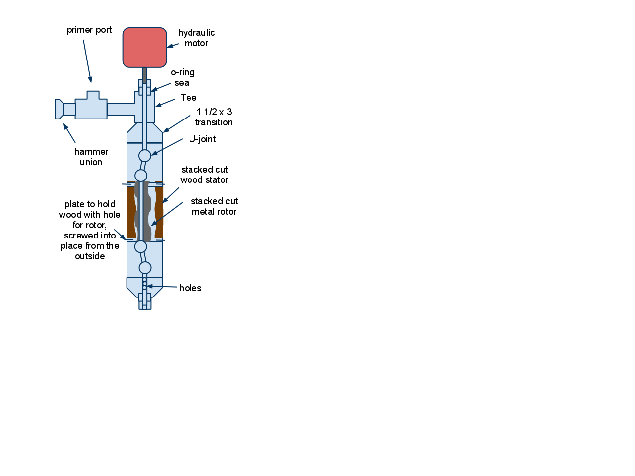
i rigged it up where i could put my hose on. but when i was screwing it all together i accidentally cracked the PVC plug at one end. wasnt sure how it woudl effect it so went ahead. it leaked from there first, at the threads. it leaked from the other end, where the o-rings should have been hodling, and also some from the collars that i only hand tightened. when i moved the T side to side it seemed to move the o-rings around and some places held better than others, indicatign to me that the o-rings were coming out of the pvc area. there were 4 orings on either end. i might try with more orings and maybe ill also get some string gasket material and see how that goes. 5/22/11 dorkmo
k i went back and made a new pvc plug with a hole. and got a better clamp for the hose hook up.
so i opened the valve it didnt seem too bad. there was a small steady leak from a few places. i could spin it by hand it seemed to do fine. next i'd like to somehow get it to spin at operating speed to see how the orings hold up. i might change it to have the water go into the T and then put some sort of hand crank on the 1" pipe. maybe in a week or two
Drill String Raising/Lowering
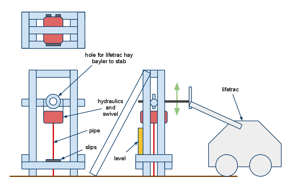
idea for a lifetrac enabled pulling apparatus google doc
square tubing could be reused on other projects after well is complete
could wooden 4x4s work? need extra support beams?
A Preliminary Design
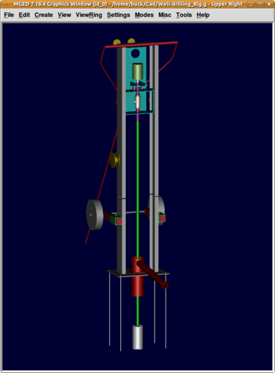
Here is a first rendering of the well drilling rig as rendered in BRL-CAD. The hydraulic pump (green) from the MicroTrac is shown mounted with the shaft downwards on the blue sliding frame which moves up and down the side tracks. The mounting of the motor to the green frame will use the same two bolt quick release system employed by the MicroTrac to allow for interoperability and quick changeovers from one device to the other. The rotating shaft from the hydraulic pump is connected to the purple section of drill string piping which stays centered in the swivel tee allowing drilling mud to flow into it and down the drill string (shown in light green). The purple section of piping is held horizontally by the holes in the top and bottom of the frame which are only slightly bigger than the purple pipe. This purple section of piping is supported vertically by the rotating bearing assembly which rides on the top of the sliding frame. If rock is encountered while drilling the small circular plate above the bearing will push the bearing down putting extra weight on the drill string. This allows weights to be hung along the back panel of the frame allowing the amount of downward force on the drill string to be manipulated. In the reverse situation, when tripping the drill string out of the hole, the purple section will pull down on the bearing causing it to move off the circular plate and against the frame below, pushing down on the frame and holding up the drill string as it is withdrawn from the well.
At ground level the the drill string passes through the red drill collar which bolts down to the gray baseplate allowing it to be easily removed or swapped for a smaller diameter collar (the square collar flange plate will be the same for all collars allowing for interchangeability). The machine currently is shown with a 6 inch inside diameter collar allowing a 6 inch well casing ti exactly fit inside it. At the bottom of the drill string a simple gray bit is shown which is just a section of 6" pipe with partially covered end caps connected to the bottom of the lowest section of drill string piping. Since the actual drill string piping is much smaller than 6 inches (probably only 3 or 4 inches at most for a water well drilling rig) the collar can also serve analogous to the function of a rotary table on an oil rig allowing a slip to be used to support the drill string when it is detached from the turning head at the top of the rig.
The vertical side tracks can either be composed of three flat pieces of steel welded along the edges to form a channel or can be made from large (~10 cm or bigger square tubing which has been cut in half lengthwise). If additional ground stability on the baseplate is required, four long steel stakes can be driven through the corners of the baseplate to prevent it from sliding. If these stakes are just simple pieces of re-bar they can even be left in place after the baseplate is removed (when the drilling rig is lifted straight up, or tipped down to one side the baseplate would just lift off the top of the stakes), these could then be cemented into the top pad when the wellhead is capped preventing it from sliding off the top of the well, or they can be removed for re-use as well.
The side tracks bolt to the baseplate and to each other with additional plates on the outside of the tracks a pair of bolts at each end (outer plates not shown). Since the bolt holes on all pieces of this side track material are 10 cm and 20 cm in from the ends of the piece they are interchangeable with or attachable to any other piece no matter whether they bolt to the baseplate, the top crown, or another section. This interchangeability on the side rails means you can build a small test rig with short rails for prototyping and shallow well drilling and then later on you can add additional height to the drill rig by adding on longer tracks letting you run deeper before having to break the drill string to add another section (making digging very deep wells much faster). Disassembling the side tracks would be easy to do (only 4 bolts per section) allowing the tracks to be disassembled for long distance transport and the re-assembled at the well site. In order to make room for the bolt heads on the inside of the tracks, the blue frame has 4 cm by 4 cm channels cut into each side; this lets the bolts securing the side tracks pass by without affecting the guiding done by the outside corners of the frame.
For short distance transport the rig can be tipped down and pulled on the wheels (a hitch could be attached at the top of the crown). When the rig is at the well site it is tipped up (which should be possible for 2 people to do) and it is held upright by the red arm on the top which will attach to a specially designed ground stake. The red support rod also prevents torsion of the top of the machine due to the length of the crossmember. The support rod can be used either in front of, or behind the drilling rig depending on the layout of the site and the ground conditions. A second mode of transport can be achieved if you want to drill many wells in a small area, for example along the edge of a field. When the rig is upright the wheels can be easily removed by removing the pins holding in the red wheel supports. Once the wheels are off the rig can be picked up by the tractor using the small red lifting brackets seen on the rails behind the sliding frame. These brackets should fit perfectly on the mounting for the tractor, it would be like picking up the bucket or any of the other front end tools. This allows the rig to be easily repositioned since the tractor can just set it down right on the wellhead. After it is set in place the red rod is secured on the front side of the rig. The tractor can then detach from the drill rig and use the bail spike to raise and lower the sliding frame (instead of using the manual winch which some builders of the rig may choose to omit entirely).
The side tracks can also be a mounting point for a simple hand cranked, direct drive winch; similar to the winches on boat trailers. The winch, shown in brown in the rendering dispenses a cable up over the two pulleys on the top of the crown. The pulley near the centerline of the machine then supports the sliding frame below it allowing it to travel freely up the center of the side channels. Instead of a hand winch and two pulleys as shown a chain hoist could also be used.
Please let me know what you think about the pictured design, once I have added the rest of the drilling equipment and after making any changes suggested here, I will post the .g file so other people can play around with it.
Drill Bits
open source tricone bit
i think we should start thinking about ways to make tricone bits
Recommend you build "drag" bit, tricone or roller cone bit rely on weight of drill string to break up rock. Most of the designs shown will not have sufficient weight on bit for tricone bit to drill rock.
- Light wehicle can be drilled & bolted to groundrock to generate enough forces for big drill and downwards drill directions. No need to carry extra mass. Water tanks are also usable to temporaly weight machine.
stack plate steel?
rivet to housing?
Drill String
welded pipe
want to look into rolling flat plate into tubes and welding seams?
Commercial drill strings have some hard steel pipe ~100m diameter (maybe welded from ~10mm plate?) and machined & welded blocks on both heads with conical threads (male+female).
Purchased Pipe
For phase I communities that don't have the ability to produce their own piping for drill string we should find suppliers for it and get price estimates. We should also find a good, common pipe size that we should use for the machine making it easy to buy drill string and once the community can produce their own piping for drill string, since it is a commonly used size they can produce extra for sale by other users (for things other than drill string).
Well Casing
After the well is finished the walls of the well need to be prevented from caving in and collapsing the well, this is the job of well casing. Well casing is usually installed after the well is drilled out (i.e. casing is not present during the drilling operations), however in very soft soil the well may need to be cased even during the drilling phase. If this is required you can drill for some distance with the largest bit you have, then case that section, then use a smaller bit to drill further, case that section with smaller well casing, etc. The well casing for most of the well can be simple pipe, approximately 4 to 6 inches in diameter for a typical well; the bottom section should have holes drilled in it and/or sections of screen to allow the water to infiltrate into the well bore from the aquifer.
could poly pipe work for well casing?
Yes, PVC pipe is often used to case small water wells, under 8"/200mm diameter borehole.
what size casing is typically used in water well?
You need a minimum of 4"/100mm to allow for installation of cast iron cylinder for India MKII or MKIII by AOV. This will also allow installation of the Afri-Dev type pump.
Mud Pump
what kind of simple designs could be utilized for pumping mud down the drill pipe?
possible plans for reuse of mud pump materials after well is drilled?
does factory farm need this type of pump for other things?
what were some of the pros and cons of the hydraulic pump used on the first drill attempt.
Wood should be replaced gum plates to improve wear resistance.
Well Pump
was the design used on first factory farm well successful? does the design need improvement?
Well - Developments Needed
Well - General
The ability to dig wells allows communities to access underground resources:
-water
-geothermal
Not to mention the power of being able to dig deep holes for support posts or pilings.
Normal heat pumpheating for typical house needs 200m deep hole or two. Typical sale price for one hole is near 5000eur per customer. (60N, granite bed rock). Hole field is also great way to store summer solar heat and use it winter. Only problem is current price for hole fields .
General Drill tool
- if Lifetrac equiped with toolarm having diffrent drill tools for wide drill purposes, 80% components (mainly lifetrac) are usable for other things after drill & mining works are done. Drill toolhead can be then store, disassemble or sell.
- General drill needs ability to drill wall and cave roof. Drill mechanisim is ~same, but support needs more axles so it is arm.
http://www.posiva.fi/files/685/Louhinta3.jpg (picture free to use for non commercial purposes)
Good Examples
- EMAS rig - amazing results for hand-dug wells:
Rock blasting
- Use non explosives methods mainly because "how to make own explosives" are too dangerous data to share public.
- Stones in Pyramids are blasted with unhydrated lime. Lime powder pressed to hole, closed with wood tap and watered. It can generate ~500Mpa pressure.
- There are lot of old "expansive concrete" patents free to use.
Links
