Industrial Robot/Research Development: Difference between revisions
| Line 59: | Line 59: | ||
===Control System=== | ===Control System=== | ||
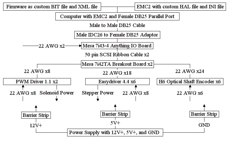
*'''Firmware''' (the XML file and BIT file) is basically configuration information for the Anything IO Board. The Firmware tells the Anything IO Board which pins are for which functions (ie. pins 1,3,5 are for step generation and pins 2,4,6 are for step direction). | |||
* | *'''Enhanced Machine Controller 2''' (EMC2) with a custom HAL file and INI file has the information required for the initialization and real-time performance of the industrial robot. | ||
* | *'''Anything IO Board''' is an intermediary between the computer and the drivers/encoders that improves real-time performance and increases the total number of physical pins available for use. | ||
* | *'''Breakout Board''' just takes the pins from the Anything IO Board and connects them individually to terminal blocks, which facilitate wiring changes. | ||
* | *'''PWM driver 1.1''' powers the solenoid valves like a relay (on or off). | ||
* | *'''Easydriver 4.4''' powers the stepper-operated needle valves. | ||
* | *'''H6 Optical Shaft Encoder''' transmits incremental changes in the angular position of an axis on the industrial robot. | ||
* | *'''Power Supply''' provides 12+VDC, 5+VDC, and GND by means of connections to barrier strips. | ||
*[[File:IndustrialRobotControlSystem.jpg]] | *[[File:IndustrialRobotControlSystem.jpg]] | ||
Revision as of 17:52, 7 September 2011
| Industrial Robot | ||
|---|---|---|
| Home | Research & Development | Bill of Materials | Manufacturing Instructions | User's Manual | User Reviews | 
| |
Overview
Research
Wanted: Brief description about the highest version of the GVCSTool
Theory
- The primary reasons for inclusion of the industrial robot in the GVCS are:
- Significant reduction in operator involvement for a wide range of procedures, resulting in more automation of tasks and more safety for humans
- High reach, payload, repeatability, and working cycle that the human arm cannot match
Relevant Links
H6 Optical Incremental Shaft Encoder Technical Drawings
Parker Vane Hydraulic Motor TB0390FP100AAAB Technical Drawings
Conceptual Notes
- Slewing bearings can have internal, external, or no gear
- Encoder coupling can be gear-to motor gear, gear-to slewing gear, or coupling-to frame attachment
- Encoder coupling-to-frame cannot be used on the same side of a hydraulic motor for an internal/external gear slewing bearing if the center encoder mount position is blocked
- A functional frame design allows mounting slewing bearings by extending the angles with plates
- If necessary, further geardown for hydraulic motors can be achieved with a planetary gearbox
- If necessary, axis torque can be increased by using multiple hydraulic motors mounted to a single internal/external geared slewing bearing
- For a worm geared slewing bearing, a support angle can be fastened as a mount face for the hydraulic motor
- Angles can share inward volumes so that their length only need be equal to the slewing bearing outer diameter
Development
Overview
- Control System includes electronics and software required for homing, teaching, and commanding sequences for actual robotic movements.
- Hydraulic System includes a hydraulic circuit that utilizes a pump, flow and directional control valves, and pressure relief valves in order to power hydraulic motors that, in turn, spin the industrial robot's 6 axes of rotation.
- Structural System includes a foundation, connecting frames, and slewing bearings which altogether comprise the physical form of the industrial robot.
Control System
- Firmware (the XML file and BIT file) is basically configuration information for the Anything IO Board. The Firmware tells the Anything IO Board which pins are for which functions (ie. pins 1,3,5 are for step generation and pins 2,4,6 are for step direction).
- Enhanced Machine Controller 2 (EMC2) with a custom HAL file and INI file has the information required for the initialization and real-time performance of the industrial robot.
- Anything IO Board is an intermediary between the computer and the drivers/encoders that improves real-time performance and increases the total number of physical pins available for use.
- Breakout Board just takes the pins from the Anything IO Board and connects them individually to terminal blocks, which facilitate wiring changes.
- PWM driver 1.1 powers the solenoid valves like a relay (on or off).
- Easydriver 4.4 powers the stepper-operated needle valves.
- H6 Optical Shaft Encoder transmits incremental changes in the angular position of an axis on the industrial robot.
- Power Supply provides 12+VDC, 5+VDC, and GND by means of connections to barrier strips.
Hydraulic System
Explanation
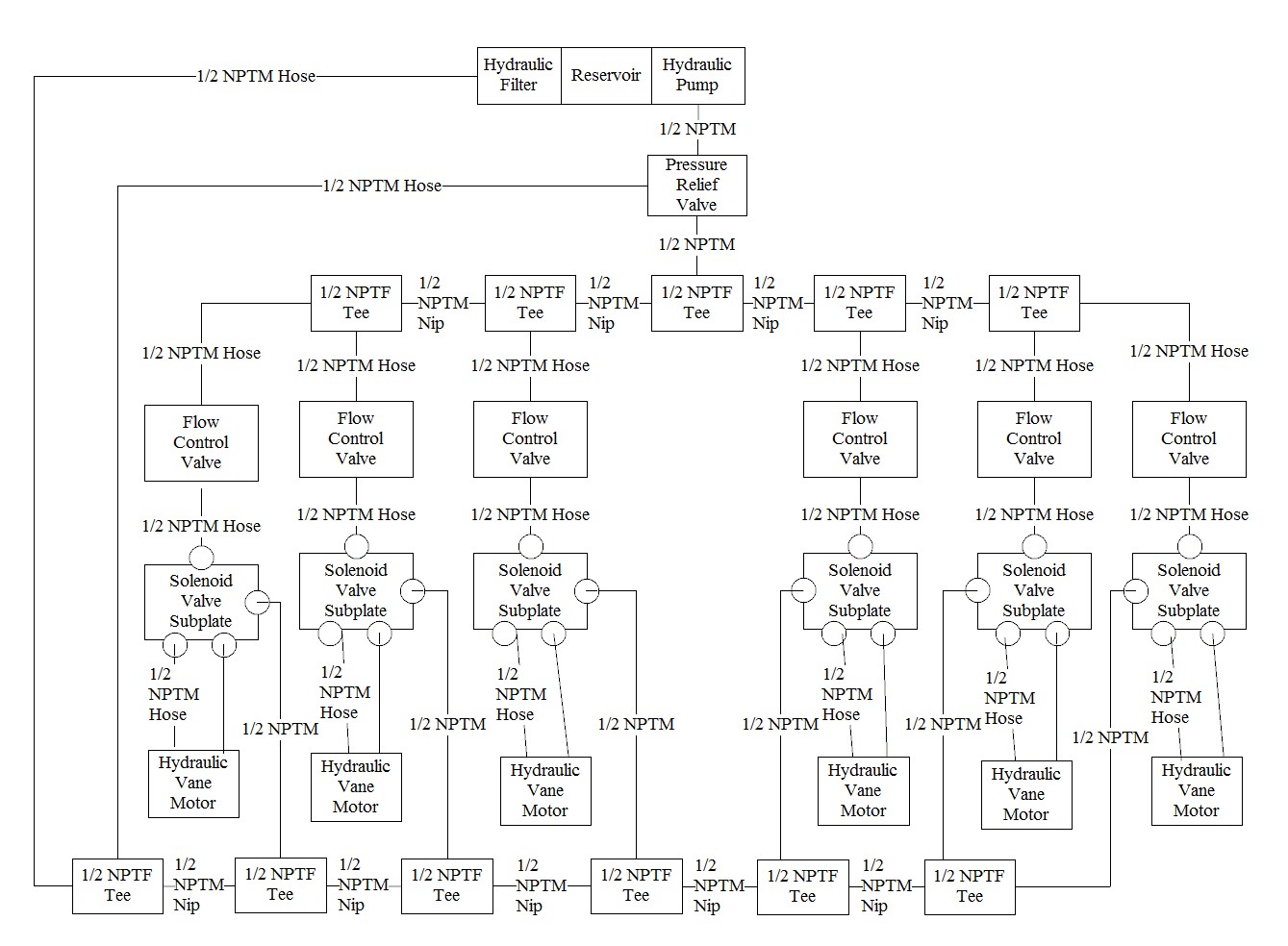
- The hydraulic filter ensures that impurities (ex. dirt, grime) in the hydraulic fluid do not enter or accumulate in the hydraulic circuit; such impurities lead to hydraulic system malfunctions.
- The hydraulic reservoir is a storage tank for hydraulic fluid to be transferred to the hydraulic pump. The reservoir holds excess hydraulic fluid to compensate for differing volumetric requirements of the hydraulic circuit at any one moment in time.
- The hydraulic pump converts mechanical power from a prime mover (ex. combustion engine) to hydraulic power as flow rate and pressure of the hydraulic fluid within the circuit.
- The pressure relief valve activates when pressure at a point in the hydraulic system approaches near a pre-determined value. Upon activation, the pressure relief valve opens a flow path between the pump and tank. The pressure relief valve ensures that pressure build-up never rises above the pre-determined value and also that continuity of flow is always maintained, without which hydraulic malfunctions occur.
- The stepper-operated needle valve is comprised of a step motor mechanically coupled to the adjusting handle of a needle valve. As the step motor shaft rotates, the needle valve adjusting handle does too, changing the flow rate of the hydraulic fluid through the needle valve.
- The 2-position 4-way solenoid-operated directional valve is comprised of a casing that contains a spool connected to a solenoid and spring. The spring keeps the spool position at one end of the valve for one flow direction; energizing the solenoid overcomes the opposing spring force, moves the spool position to the other end, and hence reverses the flow direction.
- The hydraulic vane motor is comprised of a casing with a rotor on which paddle-like "vanes" are attached. The center of the rotor is offset, hence pressurized hydraulic fluid flows through the motor and rotates the rotor, which is mechanically connected to a shaft that likewise rotates. The process is similar to the operation of a waterwheel.
Diagram
Structural System
Explanation
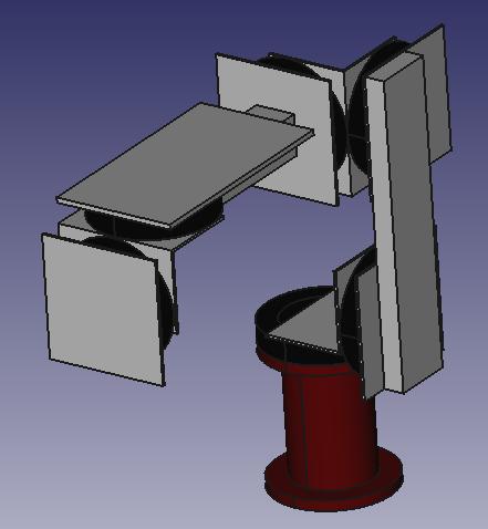
- The brown-red structural component is the foundation of the industrial robot. The foundation is simply a large flanged tube that is fastened to the ground on the bottom and fastened to a slewing bearing at the top.
- The black structural components are the slewing bearings of the industrial robot. The slewing bearings are like large ball bearings that have their outer race mounted to one frame component and the inner race mounted to another frame component; slewing bearings are designed to take radial, axial, and moment loads, and can be manufactured with an internal gear, external gear, or no gear. Multiple hydraulic motor and encoder mounting and coupling configurations are possible based on the selected type of slewing bearing.
- Steel L angles are used whenever 2 consecutive axes of rotation must be perpendicular.
- Steel bars are used whenever 2 consecutive axes of rotation must be parallel.
- Steel plates are used as a reinforcement component between a slewing bearing and a following frame component, especially when the following frame component alone would only be able to fasten to an insufficient number of bolts of the slewing bearing.
- Steel sheets are used to cover gearing mechanisms for safety reasons.
3D Drawing
Design
- Requirements
- Speed
- Throughput
- Weight
- Size Constraints
- Feed stock
- Design Description
- Calculations
- Drawings and Diagrams
- Concept and Alternatives
- Full Design Views
- Cut-away Views
- Exploded Parts View
- 3D Renders
- Decisions
- Project Team
Industry Standards
| Industry Standard | GVCSTool |
|---|
Funding
Wanted: List of expenses for prototyping and documenting GVCSTool
Peer Reviews
Wanted: Peer reviews from the scientific community regarding the R&D of GVCSTool
Experiments and Prototypes
Wanted: Empirical data on performance
Experimental Results
Prototype Notes, Observations, etc.
Failure Mode Analysis
Testing Results
Recommendations for Improvement
Encoder
Denneys on optical incremental encoders
The function of the shaft encoder is to determine the position of a motor shaft as time passes. This function is necessary for the industrial robot to perform tasks with accuracy, because the robot's movement is determined not only by the power supplied to the motors but also the load being moved.
An absolute encoder can identify different positions of the measured shaft, but is more complex than an incremental encoder. However, an incremental encoder only provides relative position information. An incremental encoder can be used as an "pseudo-absolute" by saving the relative movement information; for instance, for day 1, joint A moves 5 degrees clockwise from the home position, then day 2, joint A moves 10 more degrees clockwise; by saving the information from day 1, the microcontroller can understand that joint A has moved a total of 15 degrees clockwise from the home position, not just 10 degrees. Another method of attaining the pseudo-absolute characteristic is to record a home position each time the robot starts up. This home position is represented by a third ring on the encoder disc that has a single slit; the robot is programmed to move until sensing its home position upon which the microcontroller's angle counter is reset to zero.
Hall-effect absolute encoders -- packaged (US Digital, Renishaw) or chip -- are simple and pretty cheap, compared to optical absolute encoders. Unlike opticals, the magnetic devices usually have limited absolute accuracy (~0.5 degree) even when they have fine resolution/repeatability.
An optical incremental encoder can have a "smart" index track which has a digital pattern instead of just a single slit; this allows the microcontroller to reset its angle counter after only a small amount of movement. Gurley offers this as a product, but we could also design an open-source version (it wouldn't be hard to skirt this patent).
Combining that with schmidt trigger'd comparators, 2 digital outputs can carry signals to the microcontroller, one output to determine direction of shaft rotation and the other output to determine speed of shaft rotation. (if output B changes when output A is high, the shaft is rotating in one direction; if output B changes when output A is low, the shaft is rotating in the other direction).
Explaining Repeatability When a robotic arm is commanded to move its end-effector to a particular point in space, the end-effector may arrive a location close to the desired point but not quite. Through testing, the maximum possible inaccuracy (the distance from the desired point) can be observed and recorded. The value of this measurement is called the repeatability of the robotic arm; hence, if a robotic arm is said to have a repeatability of 1mm, then the robot's greatest margin of error when moving its end-effector to a desired point is 1mm.
Visually, the repeatability of the robotic arm can be represented by a sphere centered at the desired point of movement with a radius equal to the repeatability; when moving to that desired point, the robotic arm will always finish at a point within the sphere.
Note that the repeatability of a robotic arm is determined by a repetition test where the arm moves to and from a desired point a given number of times while measuring the inaccuracy each time it stops; it follows that the observed value of repeatability is imperfect, though a high number of trials can reduce the uncertainty.
Improving Repeatability Repeatability can be improved by lowering the deflection that occurs when the frame of the robotic arm is placed under stress. Deflection minimization can be achieved by increasing the rigidity of all components placed under stress.
When a robotic arm is commanded to move and stop its end-effector at a certain location, shaft encoders determine where the robot stops moving. Shaft encoders measure the angular position of the shaft (ex. 45.6 degrees) but must do so in intervals (ex. between 1 and 4 degrees, between 4 and 7 degrees, ...). Therefore, the resolution of the shaft encoders significantly affects the repeatability of the robotic arm (the higher the resolution, the smaller the intervals); increasing the encoder resolution will improve repeatability.
- [6] Incremental Encoder
observes and transmits digital signals based on position of gearbox output shaft to microcontroller
- [6] Support Angle
mounts onto the outer race plate at the input plate of the gearbox
- [6] Main Angle
mounts onto the support angle and provides a face upon which to mount the encoder
- [6] Shaft Coupling
connects the gearbox's support hub to the encoder's shaft
Electrical Links
- [6] Electrical connector
connects the shaft encoder to the microcontroller and power supply
Fasteners
- [12] Hub Coupling Screw
connects the coupling to the gearbox's support hub
- [6] Encoder Coupling Screw
connects the coupling to the encoder shaft
- [12] Mounting screws
mounts the encoder onto the main angle
Lead-by-Nose
- Lead-by-nose refers to a method of producing a repeatable sequence of robotic movements. After deactivating the source of hydraulic flow and allowing each axis to rotate freely, an operator moves the end-effector through the desired movements; the microcontroller notices the extent and direction of axes rotation through digital signals from the shaft encoders; correct timing is achieved by a clock circuit within the microcontroller.
Teaching
- Teaching is similar to the lead-by-nose method of recording a repeatable sequence of robotic movements. The major difference is that instead of the industrial robot being physically moved by the operator to the desired positions, the robot is digitally controlled through the positions (ex. keyboard arrow keys or a control stick)
Computerized Numerical Control
EMC2 Kinematics Module Instructions
- The enhanced machine controller 2 (EMC2) is a software program that can transform input gcode to output control signals. These control signals can be fed to the microcontroller in order for the industrial robot to perform the desired movement.
- Because the industrial robot rotates on 6 detached axes instead of moving parallel along xyz axes, the EMC2 kinematics module must be used to manipulate the control signals an additional time.
- In essence, gcode > industrial robot movement
Analysis and Calculations
Kinematic Parameters
Wikipedia on Denavit-Hartenberg Parameters (video included)
Formal Lecture Notes on Denavit-Hartenberg
- The Denavit-Hartenberg parameters define the position relationships between 2 motors of the industrial robot. More specifically, the robot has 6 motors, hence one parameter would be between motor 1 and 2; another between motor 2 and 3, 3 and 4, 4 and 5, and 5 and 6.
- The Denavit-Hartenberg parameters are as follows, for joint(i): depth(i), normal length(i), z angle (i), x angle (i).
- Joint(1): Depth(1)= , Normal Length(1)= , Z Angle(1)=90deg , X Angle(1)=*
- Joint(2): Depth(2)= , Normal Length(2)= , Z Angle(2)=00deg , X Angle(2)=*
- Joint(3): Depth(3)= , Normal Length(3)= , Z Angle(3)=90deg , X Angle(3)=*
- Joint(4): Depth(4)= , Normal Length(4)= , Z Angle(4)=90deg , X Angle(4)=*
- Joint(5): Depth(5)= , Normal Length(5)= , Z Angle(5)=90deg , X Angle(5)=*
- where * is the joint variable
Force Analysis
- Format
- Force is expressed in newtons (N)
- Maximum absolute displacement is expressed in millimeters (mm)
- Dimensions are expressed in inches (“)
- A36 Steel Specifications
- Poisson Ratio = 0.285
- Young's Modulus = 200GPa
Torque Calculations
- Required torque for each axis (in-lbs)
- Axis 1: 0
- Axis 2:
- Axis 3:
- Axis 4:
- Axis 5:
- Axis 6: 0
- Actual torque for each axis (in-lbs)
- Axis 1: 18800
- Axis 2: 18800
- Axis 3: 7800
- Axis 4: 7800
- Axis 5: 7800
- Axis 6: 7800
- Payload (lbs):
Toolchains for Toolpaths
Toolchain for Toolpaths (Electrical)
- Electrical Schematic Designer (gschem) > export ( __ filetype)> PCB Layout Creator (PCB) > export (gerber filetype)> G-code generator from gerber files (PCB2gcode) > export (gcode filetype) > Machine Controller (EMC2) > export (logic signals) > Machine ( __ ) > export (work)
Toolchain for Toolpaths (Mechanical)
- CAD (FreeCAD) > export (stl, dxf, svg) > CAM (PyCAM) > export (gcode) > Machine Controller (EMC2) > export (logic signals) > Machine (CNC milling, various) > export (work)
- In FreeCAD, a 3d mesh drawing can be exported as an stl file; alternatively, a 2d drawing can be exported as a dxf or svg file. Any of these files can then be imported in PyCAM, in which toolpaths can be generated for those drawings. These toolpaths can then be exported from PyCAM as a gcode file. EMC2 can then import the gcode file and simulate the toolpath, plus send logic signals to an external electronic controller that moves a machine to correspond to the toolpath. This toolchain allows digital fabrication to be utilized for the construction of the industrial robot.
Other
Future Development
- As various components of the industrial robot shift from commercial purchase to open source fabrication, design flexibility will increase, improving performance while reducing input resource usage.
- Based on torque calculations and scalability analysis, the industrial robot's payload can exceed 1000kg (2200lb) in future designs as necessary.


