CNC Torch Table/Research Development: Difference between revisions
No edit summary |
(→Review) |
||
| Line 382: | Line 382: | ||
*Suitability of plasma cutter? | *Suitability of plasma cutter? | ||
*Potential improvements? | *Potential improvements? | ||
==See Also== | |||
*[[Lawrence_Kincheloe_Contract2]] | |||
{{GVCS Footer}} | {{GVCS Footer}} | ||
Revision as of 15:34, 11 September 2011
| CNC Torch Table | ||
|---|---|---|
| Home | Research & Development | Bill of Materials | Manufacturing Instructions | User's Manual | User Reviews | 
| |
Hot Updates
9.28.09
First motion of the Open Source Torch Table tested with an actuator - here a marker:

Proposal
See proposal at http://openfarmtech.org/Lawrence_Proposal.pdf .
You can also see the working agreement,Lawrence Kincheloe Contract
Working updates on the blog - [[1]]
Previous Work Torch Table

The purpose of this project is to enrich both the participant and the Factor e Farm project. The scope of this specific project is to build the seeds for a MegaRap, which is a modification of the origional Torch Table designed to expand the range of build materials and capabilities. This is in the spirit of the RepRap project, but at a larger scale and lower precision. The initial goal is to design and build a torch table that can be added on to in the future but is still functional in its own right.
Documentation
The process of documenting this project goes through three steps.
- Figure something relevant by doing it, researching it, or scratching it out as an idea.
- Clarify the nugget of an idea into a written document, like a project journal. (this project has one and it resides at FeF)
- Break up the problem/rational and the steps to fix it and put them on a wiki. (this wiki)
- So far that process has resulted in this huge mess below(at the time of writing, the whole thing is one long wiki page). So after you get all that wonderful documentation done, go through and clean it up into sections and pages. Its important to keep up the stream of crappy documentation because doing it at the end, right the first time is a hassle and usually you only have time to splash documentation around liberally anyways. The important thing is to make it a coherent document at the end.
Design Rationale
- High performance torch table matching and exceedings standards of commercial counterparts
- Ready adaptability to other cutting heads (router, laser, knife, etc.)
- Rack for x, y, and z motion - cheapest, most robust solution for precise motion
- Similar design in x, y, z directions
- Minimal fabrication requriments, bolt-together design
- Spring-loaded x and y motors to maintain traction
- Support under top rail with flat ball bearings to prevent the carrage from jumping the track
- Thin gauge (16 gauge) 1 inch square tubing for light weight strength
- Simple, adjustable carriage design that clamps around the 3 inch cold-rolled rail
- Ways - simplest way according to this source is bearings on cold-rolled steel.
Working Concepts
X axis


Y axis


Z axis


Blender Design File Download
Blender Concept
 File:Factor e Torch Alpha 3.1.blend
Plasma Torch
Torch vs. Plasma Cutter
- Comes down to initial cost versus long-term cost
- Plasma cutters - consumables cost $20 for 5 new electrodes and nozzle heads
- Electrodes are rated for 45 minutes to 60 minutes for 1/2" steel
- More expensive versions state they last 4 times longer - are heavier and have better temperature control
- For anything above 1 inch, torch is better
- Can be interfaced with a computer cheaper than Torch
Desired Characteristics
We are looking for a machine rated for 1" milled steel that will cost roughly between $700-$1100. We are limited on budget because we are funded primarily through donations at the moment.
Since we want to use the machine for cnc work, we are interested in the pilot arc starting, or touch off starting. We could also use high frequency starting, but we would have to shield our motor controller and any other equipment in the area. Would it be possible to shield the plasma cutter? We want to be able to cut thin material with the torch so it is likely we will want the pilot arc starting feature.
Do you have any suggestions on a best practice method of attaching a plasma torch head on a cnc machine?
We would also be interested in a plasma cutting head that would be easier to mount. Currently in your accessories page you only list a model that is appropriate for plasma cutting by hand. Also, since this machine needs to be flexible we would also like the option of using the plasma cutting head by hand. Through looking at competitors websites, its clear that its easy to offer one or the other and switch them at the DC power inverter, but how easy would it be to add a 45 degree flexible head that can be fixed for either cnc overhang cutting or hand cutting? This seems like an easy adaption, but I might be missing something.
Also, we are interested in the engraving feature. Especially the controlled plasma pulse feature. The reason is that we are interested in precision surface removal, and gouging because we have an idea to use this machine as a plasma lathe, combined with a cnc controlled head. This isn't a requirement, but we are very interested in getting the maximum amount of utility from this tool.
Plasma Cutters Considered
- cheap ($800)
- 5 year warranty
- made in china
- cheap
- 1 year warranty
- made in america (This point is contested, maybe designed in America...)
- Out of stock/high frequency start only
- Appears to have equivalent performance to Esab Powercut 1250
- Expensive ($2700)
- Brand name
Plasma Cutter Interference Problems

The plasma cutter is currently sitting right next to the motor controller. The plasma cutter case is grounded, but the connection is made with twisted copper housing wire which needs to be checked to make sure it is actually going to ground.
From Jeff at Xylotex
Noise from plasma tables can be a problem. You should sheild and ground the motor cabling to keep them from picking up noise and condcuting it back to the drive. Proper sheilding and grounding is really important for plasma systems.
Jeff
From Mark at Everlast Forums
Running on a generator, could be a cause of some strange frequencies, depending on how "clean" the power is.
The HF generates the pilot arc. It sounds as if you are grounding the bolt on the back of the machine correctly.
But you hit upon the key: Shielding. I am not the expert on electronics or on shielding the electronics, but I can tell you that unshielded cables can be affected by the surge from the High Frequency. I think that Mike will weigh in on this. But I do think that the HF could be the real cause. It should be fixeable though.
From Wayne at Everlast Forums
You need to shield all motor controller cables and be sure the ground or drain is earth grounded on one side only. What type of motors are you using? Steppers, servo … Some of these motors require some high end wires with separated shielded twisted pairs and they run the motor power wires separately from the position feedback wires to reduce the possibility of problems. The generator may be causing the issue when it reacts to the surge demand thus causing a rapid fluctuation in power. Can you hook a recording meter or scope to it to monitor the output current and frequency? To further isolate the controls side of your system you may need to run a low cost one to one transformer on the incoming power side. I have used this method for servo driven systems when there seemed to be no other way to mitigate dirty power or outside interferences. Do you have any wiring diagrams or pictures of your system? Do you only get the feedback problem when the arc fires with the motion stationary and/or moving? Can you start the arc manually then power up the controls side to see if you have positive control after the start? Sounds like a great project you have going on here. Hope we can help. Wayne
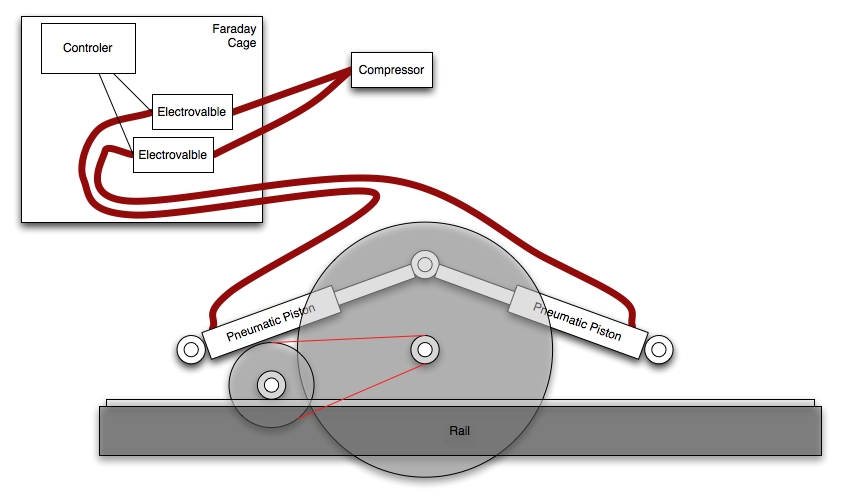
From LuisOntanon
Using a motor driven by pneumatic piston(s) could allow to shield away the controller and not have interference (Pneumatic pistons do not suffer interference) and can yield up a very precise movement.

Less EMF distributes several lines of EMF Shielding Material. Notes on shielding: low frequencies can cause more problems than high frequencies. If wires can get through your shield, so can EMI. Coaxial cables or specially woven cables can be used to reduce this problem. -gp
Plasma Cutter PC Interface


(ciruit drawn with [open source circuit simulator])
A simple relay circuit, the components depend on the plasma cutter interface. Since the Xylotex stepper controller pipes out unused pins to a second parallel port, we'll isolate the parallel port using an optoislolater and switch on a relay switch which replaces the manual torch ignition switch. If the torch allows for proportional current control, usually done with a voltage divider circuit built with a potentiometer, then we might use a pwm modulated rheostat control with the computer providing the pwm signal. If all that fails, there is alway hacking into the plasma cutter circuit board and taking over control using a microprocessor... maybe version 2.
build steps
So it turns out that because the plasma cutter comes with a pilot arc, there isn't an easy way to adjust current anyways. The reason is because the pilot arc circuit measures the current coming off the pilot arc and the work piece clamp comparing the two at low current values. Once it detects that current is flowing through the work piece clamp, it shuts off the pilot arc current pathway and ups the current for the plasma cutter. This means that there are several ways to interface with the plasma cutter circuit, but nothing out of the box. To turn on the torch head, you splice in an external switch that is controllable from the pc. To detect when the plasma cutter is good to go, you can watch for the signal pin that switches from pilot arc current to full cutting current. To adjust the cutting current, you could hijack the potentiometer from the front of the panel, which goes to the pilot arc circuit anyways. Ideally you could also tie into the voltage sensing element feedback loop of the constant current dc power supply to figure out how far away the torch head is from the surface of the work piece. This would allow for dynamic repositioning of the head.

The above is the pilot arc board. We won't be touching it but for future reference, the chip File:Mc14066bcp datasheet.pdf MC14066B is a Quad Analog Switch/Quad Multiplexer which means that it is a likely candidate for investigating when it switches the reference voltage from the pilot arc to the dial setting, it probably means that the plasma cutter is ready to cut. This would make a handy "ready to cut" signal for the pc once the signal is piped out and isolated from noise.
The below picture is the signal filter for the plasma cutter. Its the green circuit board in the picture. It has two extra holes where we can slip in our switch and even use the filter circuit to boot. This just means we need to add an external connector. The reason we chose not to go for a connector that fits the front plug is that the cost of that plug is prohibitive for what we want. Instead we are going to use a phone jack and wire together two pins for our interface.

The main board is where all the magic happens. We won't touch this board, but it is interesting to note that most of this plasma cutter could be replaced with a handful of microprocessors.

The data sheet for the solid state relay used File:AQV252G.pdf
An quick overview of how this is going to work. The PC uses a parallel port that uses 0-5 volt off/on to communicate to the outside world. This has a guaranteed minimum of 2.6mA at 2.4V. Or so says the internet. The AQV252G is a solid state relay, which means it is optically isolated mosfet relay switch. This is nice because it takes care of most of the heavy lifting design wise, so all we have to do is interface with it. To do so, we essentially turn on and off a built in LED which is coupled to the mosfet. Because every parallel port is different, it would of been a smarter move to put in a variable potentiometer instead of a single resister. Unfortunately, I just thought of this, so we are going to use a 680 ohm resistor instead and hope that the voltage level for the parallel port is on the high side.

Design rational is basically, I'm treating the torch trigger like a ac/dc signal so I don't have to worry about polarity, and I can adjust the resistance until I can guarantee the parallel port can trigger on the mosfets. Detailed construction notes when all the parts arrive...
Information about PC parallel ports. [2]
Ok, parts arrived. Here is how to put it together.

We are tyeing together two wires of the four wires in a phone wire to make a thicker wire. We only need two wires anyways. So, twist the adjoining pairs of wires so your four wires become two, tin them with solder, remove the filter board from the plasma cutter, find the input pins coming in from the torch trigger, stick the wires through the handy holes on the board, solder them to the board, and reattach into the plasma cutter.

 there it is all tucked in. Notice the bottom where the wires are soldered in place.
 All done!
Whew, ok now on to the opto-isolated control box and pc interface.
 Ok, you'll need a small project box, a female db25 connector, 680ohm resistor, a male phone chord, the solid state relay AQV252G, and a db25 cable with a male and female ends(not shown).
 Make a hole in the project box so the db25 connector can be set into the side of the box. Decide which pins will be connected to the optical switch.
 One should be ground and be connected to pin 14. Solder the solid state relay onto the project board, solder and connect the proper wires. Use small wood screws to screw into the plastic to set the connector in place. Screw the whole mess together and test it.
 it plugs into the back of the motor controller using the same sort of cable that plugs into the pc
Mounting the Plasma Cutter
We are shooting for a sideways mounted plasma cutter that forms a crooked tee with at least two mount points for the plasma cutter to rest on.
Motor Control
G-Code
Or how I actually tell the Torch Table to move.
G-code is a loose standard. That means if you take some other G Code that you did not write, there is a good chance it will not work. The reason is that each G Code interpreter, be it EMC2, RepRap motherboard, or fancy six axis robotic arm controller were all produced for a specific job which require a specific tool path, on a specific machine. Now if you're a computer scientest or programmer, you're going "wait a minute, why don't they just make the language more intelligent, add in a required machine descriptor and abstract the tool path away from the user which forces users to hand craft each part they want to make!" Which is a valid point, and I would encourage someone to come up with a better language, because G Code sucks.
G-code, ala EMC2
Or how prototype 1 is put together.
- EMC2 G-code quick lookup guide - http://linuxcnc.org/docs/html/gcode.html
- Invaluable EMC2 user generated documentation wiki - http://wiki.linuxcnc.org/cgi-bin/emcinfo.pl
- EMC2 G-code guide with regards to using a plasma cutter - http://wiki.linuxcnc.org/cgi-bin/emcinfo.pl?Plasma
Because we don't have an "arc stable, good to cut" we will use a delay instead which means that we'll have to find someplace on the material we can "burn into" while the arc stabilizes. This will have to be hand coded to some extent I am afraid.
There is a lot of good information in the manual which will be nessisary to hand craft G-code - G-code overview
The other option is to use a program to generate g code from a drawing or cad software. The problem with this is that it usually does a point by point move, where a human operator could use a loop and arc move instead to achieve the same results. Furthermore, because there is no guarantee that they conform to the same g code standards as your controller, it is likely that any g code that is automatically generated will need to be tweaked first. If it isn't apparent yet, g code is time intensive to produce. Its saving grace is that once you have it, you can run the same program over and over again.
Lets take a look at the below file that was generated using Inkscape and this G-code plugin
(Found 1 paths for AllObjects:)
G20 (All units in inches)
#1=0.5000 (Height to traverse when not cutting)
#2=0.0000 (Height to cut at)
#3=10.0000 (Tool feed rate)
#4=1.0000 (X axis scale factor)
#5=1.0000 (Y axis scale factor)
(Path has size 36.000 x 54.000)
(Path has bounding box 4.500-40.500 wide by 4.000-58.000 high)
G00 Z#1
G00 X[4.5000*#4] Y[58.0000*#5]
G00 F#3 Z#2
G01 X[4.5000*#4] Y[58.0000*#5]
G01 X[36.0000*#4] Y[58.0000*#5]
G01 X[4.5000*#4] Y[35.5000*#5]
G01 X[40.5000*#4] Y[31.0000*#5]
G01 X[13.5000*#4] Y[13.0000*#5]
G00 Z#1
G00 X[0.0*#4] Y[0.0*#5]
M2
This program has options for some basic conveniences, but its true power is that it allows for a simple conversion path from a drawn path to actual g code. That being said, I wouldn't use it for anything more complex than making holes and contours. Luckily thats what most people want it for.
For example, the # with a number following allows for macro variable replacement, so minor changes, like going from millimeter to inches, isn't such a pain.
More info can be had at by looking to the emc2 manual for information on G code.
Other sources for g code generated goodness. TBC
Xylotex


One of the channels has gone bad unfortunately and the most likely cause is that there was a loose connection which caused an intermittent short. From the documentation, it is strongly suggested to not unplug the motors while the controller is on. One reason for this is that stepper motors act like large inductors, and when an inductor is discharged they can produce high voltage spikes. Now, a loose connection can act an awful lot like unplugging the motor while turned on. All the wires were tightened down hard which should alleviate the cause but the problem still needs fixing.
From Jeff at Xylotex
Hi, The part number is A3977SEDT from Allegro Micro. These are available from www.digikey.com
The glue holding the heatisk on is thermal adhesive, to conduct heat to the sink from the chip. If you pry between the chip and heatsink, you should be able to pop it off. Do not pry between the board and the heatsink, as this could possibly rip the chip off the drive board, taking traces with it and wrecking the board.
Once the heatsink is off you can use a hot air gun to melt the solder and remove the chip. Be sure to protect the other devices on the drive board from the hot air. Or, if you are careful, you can cut all of the leads and then clean up the pads. Again be careful so as not to rip up pads and traces.
Digikey has the part for under $9 dollars, which makes this the cheapest and probably the easiest fix.
The next option is to replace the channel with a stand alone modular stepper motor controller board. RepRap has them and MakerBot Industries sells them for $20. On top of that you'll have to figure a way to wire it into the appropriate parallel port pins, which is an exercise left for the student to complete. (hint: look at the plasma controller interface)
RepRap
The RepRap project uses 12v stepper boards. These are roughly comparable with the Xylotex stepper control package. The difference is that Xylotex can step at 1/8th of a 1.8 degree step per pulse, and RepRap can step at 1/4th of a 1.8 degree step per pulse. Xylotex also has a total higher wattage potential at 24V 2A, but RepRap which runs at 12V 2A should be enough to hit the optimal energy density of the stepper motors. The only thing I would add would be a heat sink and a fan to the RepRap stepper driver so we can work the motor driver harder. Version 2 will most likely try to either incorporate a redesigned RepRap motor driver that can do 1/8th stepping or live with the standard 1/4th stepping. It is yet to be seen how useful 1/8th stepping is in practice. [3]
RepRap Response from Chris Palmer
Q. Chris, can the RepRap motherboard v1.1 suffice to handle these stepper motors for our torch table, or a smaller 4'x4' version of the same? We would like to transition away from the Xylotex closed source version. Lawrence commented on this point. What is your feedback on his comment?
A. You need stepper driver boards in addition to the motherboard for any motors, so the motherboard will drive any stepper motors. Lawrence says the reprap stepper drivers are 1/4 step, but that is not true, they are half step. The V3 stepper drivers are 1/8 step, but I don't think anybody sells them yet, so you would have to get your own PCBs made. They will only do about 2A with good heatsinking, so you won't get the full torque. The chips are rated at 2.5A, but it is very hard to get that in practice. Reprap only needs about 1.5A, so is generally moving to smaller drivers, not bigger.
Linux CNC
The Setup
We are as of Sept. 4, 2009 using an IBM ThinkPad laptop graciously donated to the cause by Inga. It has the latest EMC2 installed from the Ubuntu 8.04&EMC2 Live CD.
If you're starting from a pre-existing Linux install, like I was, then read this important user contributed wiki. I had to reinstall using the 8.4 live cd because 8.10 of Ubuntu wasn't supported.
Once you get that all installed, the best documentation available is from the user contributed wiki and the included manuals. For example, when I had trouble with getting the IBM laptop to talk to the motor controller, I used [this walk-through] to step me through a working install which lead me to the actual problem of the IBM laptop having a non-standard printer port address.
Once I got the stepper motors twitching to my every whim, I put it all down and will continue from where I left off once I get the little beasties mounted.
A quick note: this link is Very Important. It discusses how to install and use a kernel module that disables power saving features which improved our performance by an order of magnitude. Of special note, "For Hardy you don't need to compile or install it, it's already there (go to step 6)." which is what we are using because we installed off the emc2 live cd :-)
Torch Table Trouble Shooting
For those extra hard to reach bugs
- Check stepper motors
- They should turn when powered off, so the whole table should move freely. If it doesn't fix it.
- When the motor controller is powered on, with the PC disconnected, the stepper motors should be locked in place or provide significant resistance.
- If everything checks out, the motor driving circuitry and the stepper motors are at least working correctly.
- Check the PC parallel port.
- You can do this with a multimeter and LinuxCNC. If you test one of the pins under control and its jumping around like crazy then the computer is at the least sending something with the parallel port
- There are options to change the parallel port address from the default. In the case of the IBM laptop, the parallel port was 3BCH, which is a hex value.
- Check the pinout of the cable.
- In our case we used a shielded straight pass through cable, which means each pin on either side corresponds to its matched up pin on the male/female connector.
- If it's different than what you think it should be, according to whatever motor controller you're using, you can adjust the pin out in EMC2. Look up how to do this.
- Check installed version of Linux.
- In the version we used, there was an issue where the kernel drivers for 8.4 weren't compatible with 8.10 and above. This means that it installed fine but there wasn't an option for using the special real time EMC2 kernel. The fix is to reinstall using either the live CD which will leave you with a clean Ubuntu install with the software already installed (very convenient if it works), or installing from scratch Ubuntu 8.4 and installing the package seperately from [[4]]
Work piece table
I designed a modular table that could be used by itself or strapped together to make a larger table. I also designed a method to use bricks as the under surface to protect the metal the table is made from getting cut by the plasma cutter.
To accomplish this feat I chose a space frame structure made up of eight 2.5' by 2.5' by 1' cubes. They used 11 gauge 1.5" diameter square tubes and used 26 inches of tube. Some material is lost due to cutting and the exact dimensions aren't as important because the height will be adjustable with bolts on the feet.


The bricks are held in place by placing 2.5 foot long angle beams across the top of the square such that a brick can be placed so the sides of the brick rest on the walls of the angle beam, not on the apex. The weight of the brick keep the angle beams in place and the angle beams rest against the inside of the space frame to keep the bricks from pushing the angle beams apart and slipping through.
Another neat aspect of this idea is that there are several ways to adjust the height of the table. One method is to raise and lower the bolts, but this will only net you an inch or more of precise motion. The other option is to rearrange the brick pattern such that they stand taller lenghwise, this uses more bricks but also makes the table taller by several inches without doing something you might be doing anyways like switching the bricks over to a less burnt section. It is still unknown how good a work surface bricks actually are. It is hoped that they will be sufficient as they are a bountiful resource at FeF.
Review
Please submit comments here. Please review our design rationale first.
Particular points:
- Suitability of 3x1/8" cold rolled rail as a guide
- Suitability of thin gauge 1" square tubing for most of the gantry
- Structural or stability issues?
- Acceleration issues?
- Feasibility of using a laptop and compromises therefrom?
- run [realtime latency test] before getting too attached - laptops are notorious for hardware timing glitches.
- Lawrence: Performed, just not documented. We were getting in the 30-50 micro seconds range which is acceptable for right now. We have several other computers but the laptop was the only one that didn't have an immediate hardware issue.
- dust generated by plasma will get in keyboard and fan, wear out quickly. hard to replace laptop parts.
- Lawrence: Good catch. this is especially relevant since the recommended parallel cable length is 3 feet to 6 feet and the motor controller box itself has rather shortish cables. The ideal solution is to use something that is more robust and able to be isolated like an embedded processor in an enclosure. Best for version two. for now however,the best option will probably be a dust cover for an external keyboard and a foam fan filter for the motor controller and final pc configuration.
- run [realtime latency test] before getting too attached - laptops are notorious for hardware timing glitches.
- Suitability of plasma cutter?
- Potential improvements?
See Also