CNC Torch Table/Research Development: Difference between revisions
No edit summary |
No edit summary |
||
| Line 8: | Line 8: | ||
*[[Torch Table Concept]] | *[[Torch Table Concept]] | ||
*[[Plasma Cutter Design]] | *[[Plasma Cutter Design]] | ||
*[[G-code]] | |||
=Motor Control= | =Motor Control= | ||
==Xylotex== | ==Xylotex== | ||
Revision as of 13:07, 27 September 2011
| CNC Torch Table | ||
|---|---|---|
| Home | Research & Development | Bill of Materials | Manufacturing Instructions | User's Manual | User Reviews | 
| |
Overview
Research and development work relating to the  CNC Torch Table
Motor Control
Xylotex
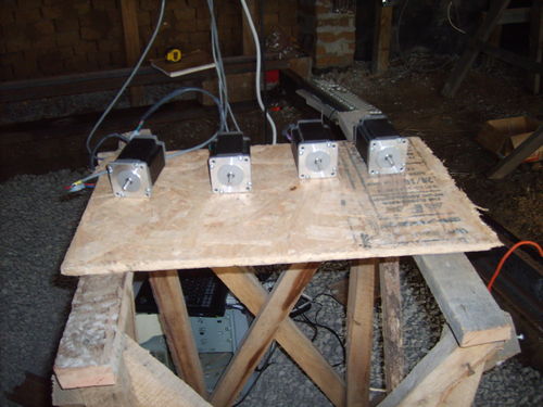
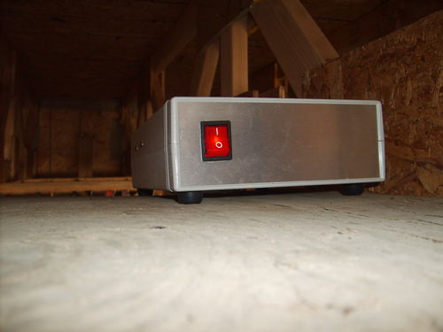
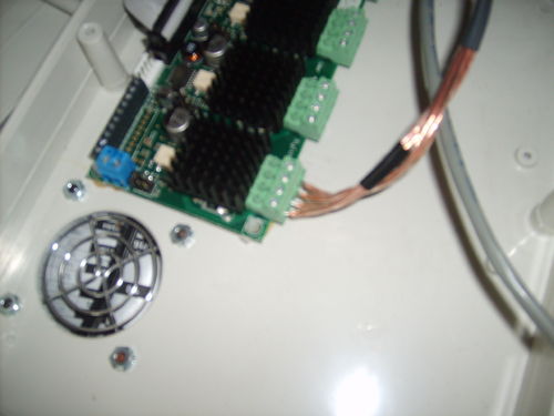
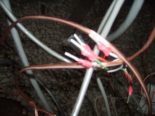
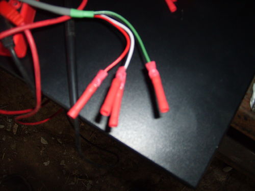
One of the channels has gone bad unfortunately and the most likely cause is that there was a loose connection which caused an intermittent short. From the documentation, it is strongly suggested to not unplug the motors while the controller is on. One reason for this is that stepper motors act like large inductors, and when an inductor is discharged they can produce high voltage spikes. Now, a loose connection can act an awful lot like unplugging the motor while turned on. All the wires were tightened down hard which should alleviate the cause but the problem still needs fixing.
From Jeff at Xylotex
Hi, The part number is A3977SEDT from Allegro Micro. These are available from www.digikey.com
The glue holding the heatisk on is thermal adhesive, to conduct heat to the sink from the chip. If you pry between the chip and heatsink, you should be able to pop it off. Do not pry between the board and the heatsink, as this could possibly rip the chip off the drive board, taking traces with it and wrecking the board.
Once the heatsink is off you can use a hot air gun to melt the solder and remove the chip. Be sure to protect the other devices on the drive board from the hot air. Or, if you are careful, you can cut all of the leads and then clean up the pads. Again be careful so as not to rip up pads and traces.
Digikey has the part for under $9 dollars, which makes this the cheapest and probably the easiest fix.
The next option is to replace the channel with a stand alone modular stepper motor controller board. RepRap has them and MakerBot Industries sells them for $20. On top of that you'll have to figure a way to wire it into the appropriate parallel port pins, which is an exercise left for the student to complete. (hint: look at the plasma controller interface)
RepRap
The RepRap project uses 12v stepper boards. These are roughly comparable with the Xylotex stepper control package. The difference is that Xylotex can step at 1/8th of a 1.8 degree step per pulse, and RepRap can step at 1/4th of a 1.8 degree step per pulse. Xylotex also has a total higher wattage potential at 24V 2A, but RepRap which runs at 12V 2A should be enough to hit the optimal energy density of the stepper motors. The only thing I would add would be a heat sink and a fan to the RepRap stepper driver so we can work the motor driver harder. Version 2 will most likely try to either incorporate a redesigned RepRap motor driver that can do 1/8th stepping or live with the standard 1/4th stepping. It is yet to be seen how useful 1/8th stepping is in practice. [1]
RepRap Response from Chris Palmer
Q. Chris, can the RepRap motherboard v1.1 suffice to handle these stepper motors for our torch table, or a smaller 4'x4' version of the same? We would like to transition away from the Xylotex closed source version. Lawrence commented on this point. What is your feedback on his comment?
A. You need stepper driver boards in addition to the motherboard for any motors, so the motherboard will drive any stepper motors. Lawrence says the reprap stepper drivers are 1/4 step, but that is not true, they are half step. The V3 stepper drivers are 1/8 step, but I don't think anybody sells them yet, so you would have to get your own PCBs made. They will only do about 2A with good heatsinking, so you won't get the full torque. The chips are rated at 2.5A, but it is very hard to get that in practice. Reprap only needs about 1.5A, so is generally moving to smaller drivers, not bigger.
Linux CNC
The Setup
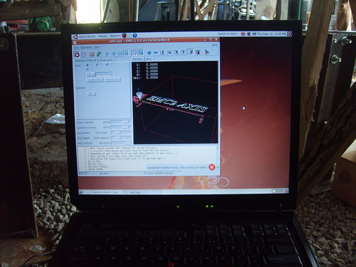
We are as of Sept. 4, 2009 using an IBM ThinkPad laptop graciously donated to the cause by Inga. It has the latest EMC2 installed from the Ubuntu 8.04&EMC2 Live CD.
If you're starting from a pre-existing Linux install, like I was, then read this important user contributed wiki. I had to reinstall using the 8.4 live cd because 8.10 of Ubuntu wasn't supported.
Once you get that all installed, the best documentation available is from the user contributed wiki and the included manuals. For example, when I had trouble with getting the IBM laptop to talk to the motor controller, I used [this walk-through] to step me through a working install which lead me to the actual problem of the IBM laptop having a non-standard printer port address.
Once I got the stepper motors twitching to my every whim, I put it all down and will continue from where I left off once I get the little beasties mounted.
A quick note: this link is Very Important. It discusses how to install and use a kernel module that disables power saving features which improved our performance by an order of magnitude. Of special note, "For Hardy you don't need to compile or install it, it's already there (go to step 6)." which is what we are using because we installed off the emc2 live cd :-)
Torch Table Trouble Shooting
For those extra hard to reach bugs
- Check stepper motors
- They should turn when powered off, so the whole table should move freely. If it doesn't fix it.
- When the motor controller is powered on, with the PC disconnected, the stepper motors should be locked in place or provide significant resistance.
- If everything checks out, the motor driving circuitry and the stepper motors are at least working correctly.
- Check the PC parallel port.
- You can do this with a multimeter and LinuxCNC. If you test one of the pins under control and its jumping around like crazy then the computer is at the least sending something with the parallel port
- There are options to change the parallel port address from the default. In the case of the IBM laptop, the parallel port was 3BCH, which is a hex value.
- Check the pinout of the cable.
- In our case we used a shielded straight pass through cable, which means each pin on either side corresponds to its matched up pin on the male/female connector.
- If it's different than what you think it should be, according to whatever motor controller you're using, you can adjust the pin out in EMC2. Look up how to do this.
- Check installed version of Linux.
- In the version we used, there was an issue where the kernel drivers for 8.4 weren't compatible with 8.10 and above. This means that it installed fine but there wasn't an option for using the special real time EMC2 kernel. The fix is to reinstall using either the live CD which will leave you with a clean Ubuntu install with the software already installed (very convenient if it works), or installing from scratch Ubuntu 8.4 and installing the package seperately from [[2]]
Work piece table
I designed a modular table that could be used by itself or strapped together to make a larger table. I also designed a method to use bricks as the under surface to protect the metal the table is made from getting cut by the plasma cutter.
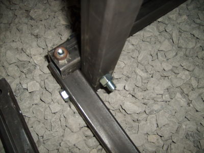
To accomplish this feat I chose a space frame structure made up of eight 2.5' by 2.5' by 1' cubes. They used 11 gauge 1.5" diameter square tubes and used 26 inches of tube. Some material is lost due to cutting and the exact dimensions aren't as important because the height will be adjustable with bolts on the feet.
The bricks are held in place by placing 2.5 foot long angle beams across the top of the square such that a brick can be placed so the sides of the brick rest on the walls of the angle beam, not on the apex. The weight of the brick keep the angle beams in place and the angle beams rest against the inside of the space frame to keep the bricks from pushing the angle beams apart and slipping through.
Another neat aspect of this idea is that there are several ways to adjust the height of the table. One method is to raise and lower the bolts, but this will only net you an inch or more of precise motion. The other option is to rearrange the brick pattern such that they stand taller lenghwise, this uses more bricks but also makes the table taller by several inches without doing something you might be doing anyways like switching the bricks over to a less burnt section. It is still unknown how good a work surface bricks actually are. It is hoped that they will be sufficient as they are a bountiful resource at FeF.
Review
Please submit comments here. Please review our design rationale first.
Particular points:
- Suitability of 3x1/8" cold rolled rail as a guide
- Suitability of thin gauge 1" square tubing for most of the gantry
- Structural or stability issues?
- Acceleration issues?
- Feasibility of using a laptop and compromises therefrom?
- run [realtime latency test] before getting too attached - laptops are notorious for hardware timing glitches.
- Lawrence: Performed, just not documented. We were getting in the 30-50 micro seconds range which is acceptable for right now. We have several other computers but the laptop was the only one that didn't have an immediate hardware issue.
- dust generated by plasma will get in keyboard and fan, wear out quickly. hard to replace laptop parts.
- Lawrence: Good catch. this is especially relevant since the recommended parallel cable length is 3 feet to 6 feet and the motor controller box itself has rather shortish cables. The ideal solution is to use something that is more robust and able to be isolated like an embedded processor in an enclosure. Best for version two. for now however,the best option will probably be a dust cover for an external keyboard and a foam fan filter for the motor controller and final pc configuration.
- run [realtime latency test] before getting too attached - laptops are notorious for hardware timing glitches.
- Suitability of plasma cutter?
- Potential improvements?
See Also
