Power Cube/Manufacturing Instructions: Difference between revisions
Tom Griffing (talk | contribs) No edit summary |
Tom Griffing (talk | contribs) No edit summary |
||
| Line 47: | Line 47: | ||
# [[PowerCube_Quick Attach Plates|Quick Attach Plates]] | # [[PowerCube_Quick Attach Plates|Quick Attach Plates]] | ||
# [[PowerCube_Oil cooler and fan mounts|Oil cooler and fan mounts]] | # [[PowerCube_Oil cooler and fan mounts|Oil cooler and fan mounts]] | ||
# [[PowerCube_Keyswtich and Choke Brackets|Keyswtich and Choke Brackets]] | |||
# [[PowerCube_Solenoid Mounting Bolts|Solenoid Mounting Bolts]] | |||
# [[PowerCube_Finish and Painting|Finish and Painting]] | |||
===Keyswtich and Choke Brackets=== | ===Keyswtich and Choke Brackets=== | ||
Revision as of 04:17, 12 December 2011
| Power Cube | ||
|---|---|---|
| Home | Research & Development | Bill of Materials | Manufacturing Instructions | User's Manual | User Reviews | 
| |
| |||||||||||
Overview
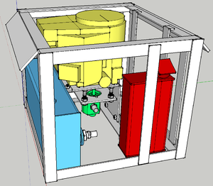
Intro to Power Cube Construction Script [[1]]
Preparation
Subassembly Fabrication
The purpose of this section is to cut the raw steel into required lengths and shapes as required for final assembly. These step includes drilling and cutting steel up to 3/8” in thickness.
- Engine & Hydraulic Pump mounts
- Quick attach mounts
- Fuel tank
- Oil Cooler Mount
- Key Switches and Choke
- Electrical cables
- Battery Mount
- Mufflers
- Hydraulic reservoir
Assembly
Power Cube assembly requires all the parts listed in the Bill Of Materials to be available and prepared as detailed in the “Fabrication” section (above). Assembly requires a welder (electric or torch) capable of welding metal 3/8” thick.
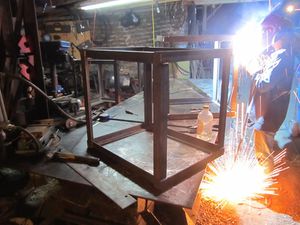
A Power Cube Jig can be very useful during the welding stage:
- Frame
- Gas tank
- Hydraulic tank
- Engine and Hydraulic Motor Mount
- Battery mount
- Quick Attach Plates
- Oil cooler and fan mounts
- Keyswtich and Choke Brackets
- Solenoid Mounting Bolts
- Finish and Painting
Keyswtich and Choke Brackets
- Clamp the keyswitch bracket to the frame as shown and weld in place.
- Clamp the choke bracket to the frame as shown and weld in place.
Solenoid Mounting Bolts
- Weld the solenoid mounting bolts to the hydraulic reservoir as shown below.
Finish and Painting
- Remove the engine if present
- Cover holes of tanks and any other place that should not be painted.
- Check all external surfaces for sharp edges and smooth with angle grinder.
- Remove any surface rust with wire brush and / or sandpaper.
- Apply a thorough coating of paint to all steel surfaces.
Install Hydraulic Components
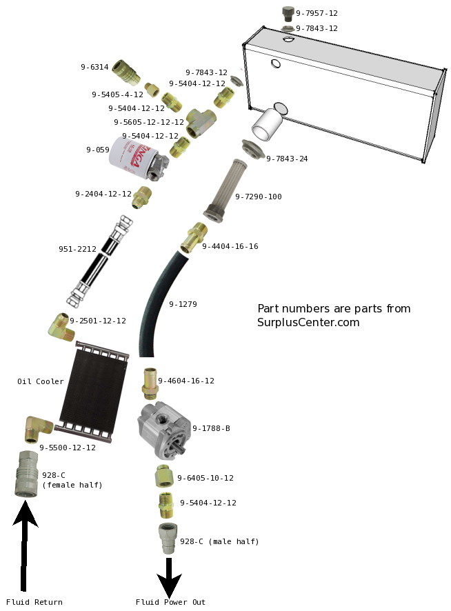
- Install hydraulic suction filter in tank and hose barb in suction filter
- Connect one end of suction hose to strainer hose barb, the other end to the hose barb on pump and secure with hose clamps
- Connect adapter, nipple and male quick coupler for fluid power output port
- Screw 3/4" male elbow into one end of oil cooler and female quick coupler to other end of elbow
- Screw 3/4" male elbow into other end of oil cooler and JIC to 3/4" NTPF swivel adapter to 1' hose
- Connect opposite end of hose to JIC to 3/4" NTPM adapter, then to filter head input
- Connect . . .
Install Solenoid
- Secure the solenoid on the bolts with two nuts.
Install Mufflers
- Unscrew the muffler from the elbow joint.
- Bolt the elbow / flange to the engine.
- Screw the muffler once again into the elbow joint.
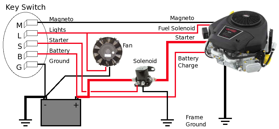
Wiring
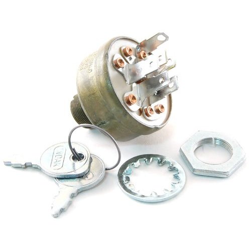
- The keyswitch has spade connectors for wiring and bolts to the frame for stability. These should be connected with matching crimp-on connectors.
- Connect the remaining wires, as in the diagram below:
- Note that the thicker lines represent the heavier wires that will carry high electrical current.
Keyswitch and Choke Installation
- Install the keyswitches in the brackets and wire as in the wiring illustration below.
- If your engine has a manual choke control, secure the choke control in its bracket.
Choke installation
- NOTE: Only necessary if your engine has a manual choke adjustment!
- Secure the engine choke knob as shown in the illustration below
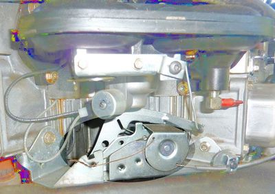
Throttle Adjustment
- The engine throttle is adjusted with a push-pull cable as shown in the image below.
Final touches
- Install engine and secure with bolts, nuts and washers
- Connect wiring to key switch and solenoid
- Connect fuel line
- Connect coupling to engine shaft
- Install hydraulic pump on coupling and secure with nuts & washers
- Install fan and hydraulic oil cooler
See Also
See also Power_Cube_Fabrication_Procedure for older model.
Work in progress by Tom Griffing - File:Powercube.odt
Update Request from Tom
We're still not done with the Power Cube documentation - it still needs some updates:
- Once the next power cube is complete, take photo of the current model and replace old photos / images on these pages: Power_Cube, Power_Cube/Manufacturing_Instructions
- Painting: Procedures, BOM entries, tools
Previous Versions
Power Cube Fabrication June 2011
