Power Cube/Manufacturing Instructions: Difference between revisions

From Open Source Ecology
Jump to navigation Jump to search
m (Fixed link)
 
(293 intermediate revisions by 5 users not shown)
Line 1: Line 1:
{{ToolTemplate|ToolName=Power Cube}}
{{GVCS Header}}
 
{{Power_Cube_Manufacturing_Instructions_Navbox}}
<br />


==Overview==
==Overview==
[[Image:Powercube4.jpg]]
<html><iframe src="https://player.vimeo.com/video/29562529?title=0&amp;byline=0&amp;portrait=0" width="500" height="300" frameborder="0" webkitAllowFullScreen allowFullScreen></iframe></iframe></html>


[[Image:Powercube4.jpg|thumb]]
<br />


===Preparation===
[[Power Cube/Intro Video Script | Intro to Power Cube Construction Script]]
'''Tools'''
*Welder
*Cutting
**Bandsaw
**Chopsaw
**Torch


==Preparation==


Assembly Instructions
# [[PowerCube_Safety|Safety]]
# [[PowerCube_Workspace|Workspace]]
# [[PowerCube_Tools|Tools]]


==Subassembly Fabrication==
Many of the items listed in the Bill Of Materials require preparation before use in assembly of the Power CubeThis includes drilling and cutting steel up to 3/8” in thickness.  These are the parts for assembling a Power Cube.
The purpose of this section is to cut the raw steel into required lengths and shapes as required for final assembly.  These step includes drilling and cutting steel up to 3/8” in thickness.


=====Engine mounts=====
# [[PowerCube_Engine & Hydraulic Pump mounts|Engine & Hydraulic Pump mounts]]
* ¼” x 8” x 12” Plate
# [[PowerCube_Quick attach mounts|Quick attach mounts]]
* ¼” x 8” x 9” Plate
# [[PowerCube_Fuel tank|Fuel tank]]
* ¼” x 2” x 2” x 8” Angle
# [[PowerCube_Oil Cooler Mount|Oil Cooler Mount]]
* ¼” x 2” x 2” x 29” Angle
# [[PowerCube_Key Switches and Choke|Key Switches and Choke]]
[[Image:EngineMount.jpg|700px]]
# [[PowerCube_Electrical cables|Electrical cables]]
# [[PowerCube_Battery Mount|Battery Mount]]
# [[PowerCube_Mufflers|Mufflers]]
# [[PowerCube_Hydraulic reservoir|Hydraulic reservoir]]


=====Hydraulic pump mount=====
==Assembly==
*¼” x 8” x 8” Plate


*[[Image:HydraulicPumpMount.jpg|400px]]
=====Quick attach mounts=====
*[2] 3/8” x 4” x 27” Plates
[[Image:QAMount.jpg]]
[[Image:QAPlates.jpg|400px]]
=====Fuel tank=====
*[2] ¼” x 4” x 8” Plates
*4” x 8” x 14 ½” Tube
*¼” x 2” x 24” Plate
* All welds assembling the tank must be quality welds, as they must not leak.  Be careful not to “over weld” the tank to the mount.
* Clean the inside of the ¼” x 4” x 8” tube and the two ¼” x 4” x 8” plates – anything left on these surfaces will end up in the gasoline and could clog the engine when started.  Tack and weld the plates on each end of the tube, taking care to orient the top plate with the filler hole as shown in the diagram below.
*Weld the 1/4” tank flange to the smaller hole.
[[Image:FuelTankMount.jpg|600px]]
[[Image:FuelTankMount2.jpg|400px]]
=====Oil Cooler Mount=====
*[2] ¼” x 2” x 24” Plates
*[2] ¼” x 2” x 22” Plates
*[2] ¼” x 2” x 1” Plates
[[Image:OilCoolerMount.jpg|400px]]
=====Key Switches and Choke=====
*[3] 1/8” x 2” x 2” x 2” Angle
[[Image:KeySwitches.jpg|400px]]
=====Electrical cables=====
*Note: The connectors can be purchased from an auto parts store – be aware that they usually require a crimper to attach to the cables.  Alternatively, 3/8” copper tubing can be used in 1 ½” long pieces instead.  Strip 1 ½” insulation from the cable, fully insert fully into 1 ½” copper tube, flatten end with a hammer and drill hole.
[[Image:ElectricalCables.jpg]]
*[2] 11” 1 gauge
*8 ½” 1 gauge
[[Image:ElectricalCables2.jpg]]
====Battery Mount====
*[2] ¼” x 2” x 2” x 4 3/4” Angle
*[2] ¼” x 2” x 5/8” Plate
[[Image:BatteryMount.jpg|400px]]
====Hydraulic reservoir====
*[2] ¼” x 6” x 12”
*6” x 12” x 27 ½” Tube
*2” x 2 ¼” x 1/8” Tube
* All welds assembling the reservoir must be quality welds that do not leak.  Be careful not to “over weld” the reservoir. 
* Clean the inside of the tube and the two end plates – anything on these surfaces will end up in the hydraulic oil and could damage the pump or cylinders.
* Tack and weld the 6” x 12” plates to both ends of the 6” x 12” tube.  Pay attention to the orientation of the plate with the filler hole and the side of the tube with other holes – see the diagram below.
[[Image:HydraulicReservoir.jpg]]
* Tack and weld the strainer extension tube to the tank, centered around the strainer hole.
* Insert the strainer into the flange and insert it into the strainer extension tube – verify that it slides without binding or bottoming and that the flange is flush with the end of the tube.  Remove the strainer from the flange, then tack and weld the flange to the tank.
CAUTION: Keep the strainer away from the welding, as its thin wires burn easily.
* Suction strainer, weld-in flange, 2” x 2 ¼” x 1/8” tube:
[[Image:HydraulicReservoir2.jpg]]
==Assembly==
Power Cube assembly requires all the parts listed in the Bill Of Materials to be available and prepared as detailed in the “Fabrication” section (above).  Assembly requires a welder (electric or torch) capable of welding metal 3/8” thick.


A [[Power Cube Jig]] can be very useful during the welding stage.
A [[Power Cube Jig]] can be very useful during the welding stage:
 
====Top / Bottom Rectangles====
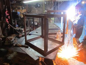
*Position two ¼” x 2” x 2” x 29” pieces angle iron on top of two 27” angle pieces as shown below.  Check that all joints are square, then tack and weld joints.
[[Image:PowerCubeAssemblyFrame1.jpg]]
*With one welded rectangle on the bottom, position the 24” pieces outside corner joints as shown below.  Check that the angles are square, then tack and weld.
[[Image:PowerCubeAssemblyFrame2.jpg]]
*Position the second rectangle as shown below, then tack and weld.  Inspect all corners to verify secure welds.
[[Image:PowerCubeAssemblyFrame3.jpg]]
 
====Gas tank====
 
*Screw the 1/4" hose barb into the 1/4 NPT flange welded into the gas tank.
*Perform a “soap bubble” test on the tank.  Securely cover the larger hole (use something like strong tape), pressurize the tank using the smaller hole and cover the tank surface with soapy water.  Look closely for new bubbles, mark any leaks and re-weld securely.  Repeat soap bubble test if re-welded.
*Tack and weld the gas tank mount (¼” x 2” x 24” plate) to the frame.
*Tack and weld the gas tank to the gas tank mount as shown below.
*[[Image:PowerCubeAssemblyGas2.jpg]]
 
====Hydraulic tank====
 
*Perform a “soap bubble” test on the tank by securely covering the larger hole (use something like strong tape), pressurizing the tank using the smaller hole and cover the tank surface with soapy water.  Mark any leaks and re-weld securely.  Repeat soap bubble test if re-welded.
*Weld it to the frame as shown with 4 1” welds.  The tank is ¼” and it can be easily damaged by over-welding.  Spacers may be needed on the sides near the top to keep everything snug.
 
====Engine Mounts and Hydraulic Motor Mount====
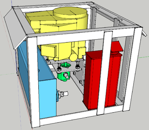
*Position the ¼” x 2” x 2” x 29” angle 12 ½” from the hydraulic tank (see diagram below). Tack and weld it to the frame.
[[Image:PowerCubeAssemblyMounts1.jpg]]
*Place the ¼” x 8” x 8” plate on the angle iron and secure with two bolts.
*Place the ¼” x 2” x 2” x 8” angle on top of the ¼” x 8” x 12” plate, align the bolt holes and  secure with two bolts.  Align this assembly with the ¼” x 8” x 8” plate in the prior step and position the angle against the hydraulic tank, 3” below the tank top as in the diagram below, then tack and weld to tank.*<image>
*Tack and weld the corner formed by the two 8” plates.
*Examine the engine shaft – it should be 3” long.  If longer, cut the shaft to 3” long.
*Place the engine on its mounting plate and verify that the shaft extends through the hole.
====Battery mount====
*Weld the ¼” x 2” x 5/8” plates to the ends of the ¼” x 2” x 2” x 4 3/4” plates as shown below.
[[Image:PowerCubeAssemblyBatteryMount1.jpg]]
*Weld the two mounts to the angle iron and tank to form a rectangle for the battery as shown below.*<image>
*After the mount has cooled, lower the battery into the rectangle to verify it fits properly.


====Oil cooler and fan mounts====
::[[Image:Pcframeweld.jpg|thumb|Power Cube Frames welding - 45 minutes per frame with one person assisting on jig clamping.]]
*Position the two ¼” x 2” x 22” plates to the outside of the frame, adjust so the oil cooler mounting bolts match the holes in the plates and is positioned as in the diagram below. Tack and weld the mounts in to the frame.  Verify that the oil cooler bolts match the holes in the mounts.
*Use the mounting holes in the fan shroud and the oil cooler width for positioning the mounting plates as shown in the diagram below.  Position the four ¼” x 2” x 1” plates, then tack and weld.  Position the two ¼” x 2” x 24” plates against the 1” plates, then tack and weld.  Place the fan on the supports and mark the mounts with bolt hole positions.  Place the bolt heads against the fan mounting plate and weld in place.  Verify that the bolts match the holes in the fan.  Inside the frame, adjust the fan position to to position fan shroud ¼” from oil cooler fins.  Be careful with radiator as the delicate fins are easily bent and damaged.*


====Solenoid Mounting and Installation====
# [[PowerCube_Frame|Frame]]
* Weld the solenoid mounting bolts to the hydraulic reservoir as shown below.  Once cooled, secure the solenoid on the bolts with two nuts.
# [[PowerCube_Gas tank|Gas tank]]
[[image:SolenoidMount.jpg]]
# [[PowerCube_Hydraulic tank|Hydraulic tank]]
# [[PowerCube_Engine Mounts and Hydraulic Motor Mount|Engine and Hydraulic Motor Mount]]
# [[PowerCube_Battery mount|Battery mount]]
# [[PowerCube_Oil cooler and fan mounts|Oil cooler and fan mounts]]
# [[PowerCube_Solenoid Mounting Bolts|Solenoid Mounting Bolts]]
# [[PowerCube_ThrottleSwitchMounts|Keyswitch and Throttle mounts]]
# [[PowerCube_Quick Attach Plates|Quick Attach Plates]]
# [[PowerCube_Finish and Painting|Finish and Painting]]
# [[PowerCube_Install Hydraulic Components|Install Hydraulic Components]]
# [[PowerCube_InstallEnginePump|Install Engine and Hydraulic Pump]]
# [[PowerCube_Install Solenoid|Install Solenoid]]
# [[PowerCube_Install Mufflers|Install Mufflers]]
# [[PowerCube_Wiring|Wiring]]
# [[PowerCube_Throttle|Install Throttle Control]]


====Keyswitch Brackets and installation====
==Final touches==
* Weld the 1/8” x 2” x2” x 2” angle brackets to the frame in the positions shown below.  Note that the keyswitch brackets have larger holes than the choke bracket.
# Install engine and secure with bolts, nuts and washers
[[image:KeyswitchBracket.jpg]]
# Connect wiring to key switch and solenoid
* Install the keyswitches in the brackets and wire as in the wiring illustration below.
# Connect fuel line
[[image:KeyswitchWiring.jpg]]
# Connect coupling to engine shaft
# Install hydraulic pump on coupling and secure with nuts & washers
# Install fan and hydraulic oil cooler


====Choke Bracket and installation====
* Weld the 1/8” x 2” x2” x 2” angle bracket to the frame in the positions shown below.
* Secure the engine choke knob as shown in the illustration below
[[image:ChokeBracket.jpg]]


====Throttle Adjustment====
==See Also==
* Use a wire to permanently set the throttle adjustment to full throttle as shown below
[[image:ThrottleAdjustment.jpg]]
 
===See Also===
See also [[Power_Cube_Fabrication_Procedure]] for older model.


Work in progress by Tom Griffing - [[File:powercube.odt]]
Work in progress by Tom Griffing - [[File:powercube.odt]][[File:powercube.pdf]]


[[Image:PowerCube.skp|PowerCube Sketchup Drawing]]


==Previous Versions==


[[Power Cube/Manufacturing Instructions/Fabrication June 2011|Power Cube Fabrication June 2011]]
[[Power Cube/Manufacturing Instructions/Fabrication June 2011|Power Cube Fabrication June 2011]]
{{GVCS Footer}}

Latest revision as of 13:02, 6 January 2012


Power Cube
   Home  |  Research & Development  |  Bill of Materials  |  Manufacturing Instructions  |  User's Manual  |  User Reviews    Power Cube.png


Overview

Powercube4.jpg


Intro to Power Cube Construction Script

Preparation

  1. Safety
  2. Workspace
  3. Tools

Subassembly Fabrication

The purpose of this section is to cut the raw steel into required lengths and shapes as required for final assembly. These step includes drilling and cutting steel up to 3/8” in thickness.

  1. Engine & Hydraulic Pump mounts
  2. Quick attach mounts
  3. Fuel tank
  4. Oil Cooler Mount
  5. Key Switches and Choke
  6. Electrical cables
  7. Battery Mount
  8. Mufflers
  9. Hydraulic reservoir

Assembly

Power Cube assembly requires all the parts listed in the Bill Of Materials to be available and prepared as detailed in the “Fabrication” section (above). Assembly requires a welder (electric or torch) capable of welding metal 3/8” thick.

A Power Cube Jig can be very useful during the welding stage:

Power Cube Frames welding - 45 minutes per frame with one person assisting on jig clamping.
  1. Frame
  2. Gas tank
  3. Hydraulic tank
  4. Engine and Hydraulic Motor Mount
  5. Battery mount
  6. Oil cooler and fan mounts
  7. Solenoid Mounting Bolts
  8. Keyswitch and Throttle mounts
  9. Quick Attach Plates
  10. Finish and Painting
  11. Install Hydraulic Components
  12. Install Engine and Hydraulic Pump
  13. Install Solenoid
  14. Install Mufflers
  15. Wiring
  16. Install Throttle Control

Final touches

  1. Install engine and secure with bolts, nuts and washers
  2. Connect wiring to key switch and solenoid
  3. Connect fuel line
  4. Connect coupling to engine shaft
  5. Install hydraulic pump on coupling and secure with nuts & washers
  6. Install fan and hydraulic oil cooler


See Also

See also Power_Cube_Fabrication_Procedure for older model.

Work in progress by Tom Griffing - File:Powercube.odtFile:Powercube.pdf

File:PowerCube.skp

Previous Versions

Power Cube Fabrication June 2011

The Global Village Construction Set
Habitat CEB Press Cement Mixer Sawmill Bulldozer Backhoe
Agriculture Tractor Seeder Hay Rake Well-Drilling Rig
Microtractor Soil Pulverizer Spader Hay Cutter Trencher
Bakery Oven Dairy Milker Microcombine Baler
Industry Multimachine Ironworker Laser Cutter Welder Plasma Cutter
CNC Torch Table Metal Roller Rod and Wire Mill Press Forge Universal Rotor
3D Printer 3D Scanner CNC Circuit Mill Industrial Robot Chipper Hammermill
Drill Press Induction Furnace
Energy Power Cube Gasifier Burner Solar Concentrator Electric Motor Generator Hydraulic Motor
Steam Engine Heat Exchanger Wind Turbine Pelletizer Universal Power Supply
Nickel-Iron Battery
Materials Aluminum Extractor Bioplastic Extruder
Transportation Car Truck

Imprimante 3D Scanner 3D Extracteur d'Aluminum Pelleteuse Four à Pain Presse à balles de paille Extrudeuse à bioplastiques Bulldozer Voiture Presse BTC Betonnière Broyeur à marteaux Imprimante de circuits électroniques Table de découpe numérique Trayeuse Perçeuse à colonne Moteur électrique Gazogène Faucheuse Râteau à foin Moteur hydraulique Fourneau à induction Bras robotisé Poinçonneuse Découpeur Laser Laminoir à plaques Microcombine Microtracteur Multimachine Batterie Ni-Fe Machine à granulés Torche plasma Power Cube Presse hydraulique Laminoir à barres et fils de fer Pulvérisateur de terre Scierie Semoir Concentrateur solaire Roto-bêche Moteur à vapeur Echangeur de chaleur Tracteur Fraiseuse de tranchée Camion Alimentation électrique universelle Rotor universel Poste de soudure à l'arc Plateforme de forage de puits Eolienne

Key Design Planning Prototype Almost done Full Release