GVCS Home List
3D Printer Research and Development
The OSE printer is called D3D - for Distributive Enterprise 3D Printer. For Current Work see 3D Printer Genealogy.
Overview
3D Printers are a subset of CNC machines: they use stepper motors to move along X, Y, and Z axes according to gCode - essentially a text file with thousands of lines of coordinates and special commands (such as "return to origin" or "set nozzle temperature"). As motors on each axis moves the nozzle through 3D space, an additional motor feeds plastic filament through a heating element, very much like an automatic hot glue gun.
The software that turns a 3D model (such as an .stl or .obj) into instructions telling the printer how to move is called a "slicer" - it slices a model into layers that will stack up to make the finished object.
Many options exist for controlling the printer with your computer - nowadays several "slicers" can also connect to the printer directly, streamlining the printing process.. As a central backbone of Digital Fabrication, the end goal of 3D printers is to be able to print anything.
Genealogy
See full genealogy at 3D Printer Genealogy
Details
Types of 3D Printers
Printing Process
(just adding a note here, please move where it fit better) To improve movement speed/accuracy of the printer head i was thought about a dual motor set (each axis) coupled with a differential gear-set so would be possible to reduce or multiply output turns with a digital controller that regulate the ratio of the two motors rotation. (not sure how to implement this and not sure it may be so effective, i just believe this may open for bigger volume printers (3m cube hypothesis). (adexmont 18/nov/2018)
Applications
http://www.instructables.com/id/3D-Printing-3D-Print-A-Solderless-Circuit-Board/
https://www.reddit.com/r/functionalprint
http://readwrite.com/2014/01/31/why-you-want-a-3d-printer-in-your-home
http://www.thingiverse.com/thing:113865
http://www.thingiverse.com/explore/newest/tools
http://www.treehugger.com/lawn-garden/garden-3d-10-things-you-can-3d-print-your-garden.html
http://3dprint.com/34873/3d-printed-lawn-mower/
https://www.pinterest.com/pin/412712753326603895/
https://www.pinterest.com/pin/412712753326427241/
https://i.materialise.com/blog/redesigning-the-bike-frame-james-novaks-experiment-with-3d-printing
http://design-milk.com/keystones-studio-minale-maeda/
http://www.instructables.com/id/Open-Source-3D-Printed-Water-Filter/
https://www.pinterest.com/pin/412712753325305467/
https://all3dp.com/3d-printed-laptop-case/
Product Ecology
| From | Uses | Creates | Enables |
|---|---|---|---|
|
Components
|
|
Status
See past work related to Factor e Farm at RepRap Build.
Currently 3D printer designs are being researched, with the goal of full integration into the Product Ecology of GVCS technologies.
3D printer technology is currently undergoing a flourishing of innovation. As a relatively new technology (2003), many experimental designs and techniques are being explored by thousands of groups worldwide.
See D3D_Landing_Page for the most recent work on this machine
See Also
- Comparison of 3D Printers
- RepRap Build
- Equipment/Lulzbot_a0_101
- Equipment/Taz
- RepLab
- 3D Ceramic
- Stepper Motor
- MIT Machines that Make
- Electron Beam Melting
- Sintering
- Ball Mill
- RepRap MetalicaRap subproject, investigating inexpensive, self-replicating electron beam melting machine design for 3D metal object and solar cell printing
- Cermets, materials that may be suitable for 3D ceramic printing techniques but give material properties superior to those of either metals or ceramics
Further reading
http://www.gifted.uconn.edu/confratute/pdf/HR2015/3D_Printing-Luria-Hack.pdf
| GVCS Home List | ||
|---|---|---|
| Home | Research & Development | Bill of Materials | Manufacturing Instructions | User's Manual | User Reviews | File:GVCS Home List.png | |
Overview
3D Scanners enable near-instantaneous input of spatial data into digital systems. The technology is currently undergoing a massive flourishing of innovation as the underlying hardware becomes ubiquitous. As a part of the GVCS 50, it enables a suite of powerful applications.
Applications
- CAD
- Rapid Prototyping
- Workshop Control
- Automation Programming
- Robotic Systems
- Training
Details
Product Ecology
| From | Uses | Creates | Enables |
|---|---|---|---|
|
Components |
See Also
- Open Source 3D Scanning/Motion Capture Construction Set
- Open Source Design Software Construction Set
- 3D Printer
- Kinect Hacks
| GVCS Home List | ||
|---|---|---|
| Home | Research & Development | Bill of Materials | Manufacturing Instructions | User's Manual | User Reviews | File:GVCS Home List.png | |
Overview
The Aluminum Extractor extracts raw aluminum from alumina common clay (alumina silicate).
Detail
Using a closed-loop cycle involving hydroflouric acid and a large amount of electricity, it is possible to extract raw aluminum directly from clay deposits. This is in contrast to the typical aluminum extraction technique from strategic bauxite mineral reserves.
There is posibility also to produce bauxite from very common feldspar mineral (sand) and carbon dioxide. This is natural process that produce clays, but it is posible to speed up usable level with increasing carbon dioxide partial pressure. Easy source for carbon dioxide are biogas reactors. Biogas cleaning produce large amounts pressurized carbon dioxide water solution. It is even posible to directly feed pressurized biogas through feldspar sand column and combine both process.
Alumium electrolyze process should be combined to localized power grid and its power consume should be tied to grid frequency after 50.5Hz or 60.5hz it should start itself and come full power until 51.0Hz or 61Hz so alumium making can be used to dump excess energy. Very useful combined with windpower.
Product Ecology
| From | Uses | Creates | Enables |
|---|---|---|---|
|
Components |
Components
See Also
- Blog Post
- Aluminum Extraction From Clays
- Molten Oxide Electrolysis - carbon free process that goes directly from ore to pure metal with pure oxygen as a byproduct
- NASA's page on MOE
- Youtube: Donald Sadoway at EmTech MENA 2019: Steel Production without Co2 Emissions
- Metal Refining
- Aluminosilicate chemistry
Overview
The Backhoe is a piece of excavating equipment used for digging holes and trenches.
Versions
Backhoe 4
No real plans for Backhoe 4 as of Oct 2013. That's just a place to record ideas for a future version.
Backhoe 3
Under active development as of Oct 2013
Backhoe 2
Plans and photos from the 6 in 60 campaign. See Cory Shenk Log for iterations of the design.
- This is the most recent version of the backhoe that I have upon the end of 6 in 60: File:Backhoe deep dig.skp
- We were never able to completely build it but we did complete sections and components. Check Leandra's Log and Luca's Log for any other information. We spent a decent chunk of time working on these together.
Bucket
- Parts for the body of the bucket. I used three pieces that were 4 inches wide as you can see in the photo. Two should be replaced with an 8 inch wide piece of the same length. It reduces the amount of welding required and adds strength to the bucket.
- You can see two pieces have already been welded. This should be cut out of one piece of steel.
- I allowed myself extra room on the pieces that I cut for the sides of the bucket. This allowed some wiggle room when assembling the entire thing.
- Step by Step in Photos
- The connection points should be revisited for better attachment to the stick. See Stick Design.
- There was often physical conflict where points attached that had square corners (in the case of the bucket and in other areas, usually cylinders). It might be a good practice to simply always notch them off or round the corners with the torch, or fabricate a rounded blade for the iron worker.
- The teeth of the bucket are bolted on so that they can easily be removed. This seems unnecessary, especially in a final version.
- I cannot determine how the shape of the bucket will affect its performance. This will need to looked into upon completion.
Stick
- Although we never reached the point of assembling the entire Boom and Stick to the Pivot, my guess (based off of many experiences in that workshop) is that there would have been conflict with the bolts and cylinders within the range of motion.
- To limit the amount of times that this occurs it would be beneficial to draw very exact models of bolts, washers, nuts, etc. Included with these should also be cylinders of various sizes, especially the sizes that would be used frequently.
- One variable that would be tricky account for is the way that beams and plates fit together.
- Is it possible to create warehouse pieces that include variables like these?
- 1
- 2
- 3
- As you can see in photos 1, 2, and 3, the triangular design that allows greater range of motion for the bucket had to be made wide to clear the bolts. This resulted in a lot of side to side movement of these pieces which is not ideal, especially under load.
- One possible solution would be to weld the two beams instead of bolting. This would allow the triangular component to rotate along the side of the stick, reducing the play.
- 4
- If bolts are still used then the method of connecting the pieces needs to be addressed. We used threaded rod because we were in a rush and did not have the proper materials on hand. Threaded rod is decidedly weaker than a smooth rod. A tractor pin, or its equivalent, would be better, but it is still a great distance to span.
- 5
- This design employs 4 points of rotation. I was attempting to mimic the designs that I found in most commercial backhoes.
- 6
- 7
- Here are some photos that I referenced from a quick Google search:
Pivot
Cylinder - [5]
- The greatest difficulty with the pivot (and every other component we tried to build) was that the holes did not line up which made assembly difficult. The pivot had many areas that required bolts to pass through along with two three inch pins. This exacerbated the problem.
- We found that the best way to assemble was to build the pivot plates AROUND the pin and then bolt the plates to the corresponding tubing.
- The collars cut for the pivot plate were slightly different in width. This caused an irregularity in plate width once they were welded in place.
- The greatest challenge that we had with the pivot was coming up with a design to make the pivot move from side to side. Commercial backhoes have a cylinder that runs in between the top and bottom of the pivot and connects to a "C" shaped piece. Due to lack of time we were not able to come up with anything that would mimic this in design or functionality.
For the Future
- make sure the holes align
- build around the pin
- streamline the pivot (it is very heavy)
- Design with side to side motion in mind
Backhoe 1
Main page for the Backhoe 1.
Details
They are typically mounted on the back of a tractor or front loader, this one is mounted on a LifeTrac. It consists of a digging bucket on the end of a two-part articulated arm. The section of the arm closest to the vehicle is known as the boom, and the section which carries the bucket is known as the dipper or dipperstick (the terms "boom" and "dipper" having been used previously on steam shovels). The boom is attached to the vehicle through a pivot known as the kingpost, which allows the arm to slew left and right, usually through a total of around 200 degrees. Modern backhoes are powered by hydraulics.
The backhoe is one of the most basic dirt working tools and is a common attachment to many small tractor and skid-steer vehicles. It can be used for digging trenches for foundations, digging up material to make compressed earth blocks, digging waste pits, and many other common building/farming tasks. Furthermore, by attaching a chain to the bucket, the backhoe can be used to lift and transport heavy loads such as engine blocks, battery packs, long pieces of pipe, etc.
Commercially manufactured backhoes vary greatly in their size and capabilities and therefore vary significantly in price. A quick google search seems to indicate that relatively small, simple devices like the one we are considering range from 2 to 4 thousand dollars with more sophisticated attachments approaching 10 thousand dollars.
Product Ecology
Made with
Creates
Videos
See Also
| GVCS Home List | ||
|---|---|---|
| Home | Research & Development | Bill of Materials | Manufacturing Instructions | User's Manual | User Reviews | File:GVCS Home List.png | |
Overview
The bakery oven is a device for heating various forms of dough into breads and other baked goods.
Detailed Description
The bakery oven provides a seal-contained volume in which various forms of dough can be placed for temperature-controlled and timed heating. The bakery oven accommodates trays for multi-level baking as well as accessibility for opening, cleaning, and performing maintenance.
Solution Statement
The bakery oven fulfills the role of expanding the food possibilities attained through grains, being the final step to a fully prepared, edible meal.
The bakery oven completes an agricultural pathway for food that involves the harvesting and use of grain.
| From | Uses | Creates | Enables |
|---|---|---|---|
|
Components
|
will need a mill too like: link small mills
Status
The Bakery Oven is currently in the research phase of product development.
See Also
| GVCS Home List | ||
|---|---|---|
| Home | Research & Development | Bill of Materials | Manufacturing Instructions | User's Manual | User Reviews | File:GVCS Home List.png | |
Overview
A Baler compresses hay and other light and dispersed materials into more compact bales.
Detail
A Baler is a piece of farm machinery used to compress a cut and raked crop (such as hay, cotton, straw, or silage) into compact bales that are easy to handle, transport and store. Several different types of balers are commonly used, each producing a different type of bales – rectangular or cylindrical, of various sizes, bound with twine, strapping, netting, or wire.
Product Ecology
Uses
 Induction Furnace - Steel
 CNC Torch Table - Parts
Works with
 Tractor - Mounting
 Power Cube - Power
 Pelletizer - Pellets
Creates
- Bales
Components
- Frame
- Roller
- Hydraulic Motor
Status
About to enter the prototyping phase as a part of the GVCS Rollout Plan, the Baler is soon to be reverse engineered and upgraded to meet OSE Spec.
Internal Links
External Links
| GVCS Home List | ||
|---|---|---|
| Home | Research & Development | Bill of Materials | Manufacturing Instructions | User's Manual | User Reviews | File:GVCS Home List.png | |
Overview
The Bioplastic Extruder enables plastics production.
"Plastics extrusion is a high volume manufacturing process in which raw plastic material is melted and formed into a continuous profile. Extrusion produces items such as pipe/tubing, weather stripping, fence, deck railing, window frames, adhesive tape and wire insulation." - (wikipedia)
Detailed Description
We aim to develop computer-controlled tools that can make plastic parts of any shape. 'Extrusion' means squeezing out a long shape; extruding a circle gives you a cylinder. Extruded plastic forms include sheets, tubes, and others. Greenhouse glazing made of polycarbonate, or UV-stabilized polyethylene, water pipes for plumbing and irrigation, plastic shapes and sheets are all doable with slight modifications of a basic extruder. The key may be a ram extruder (simple design) with inductive heating, to which various dies are adapted for profiles (extrusion), or molds for shapes (injection molding), or blowers and molds (blow molding).
With these tools, cheap feedstocks can produce very expensive products. For instance, polyethylene resin costs less than 15 cents/lb (at a density of 50 lb/cubic ft (800g/l)). When extruded into panes of Solexx glass, the end product costs $1/square foot ($10.76/m2). This makes the end product about 20 times more valuable than the feedstock. If an extruder is available - combined with the know-how - then localized production of such glazing could probably yield cost predictions of something marginally higher than material costs, under the DIY-flexible enterprise scenario.
The challenge is procuring the know-how for extruder fabrication and material extrusion. The material costs are expected to be around $5k for the machine - structure, hydraulic ram, inductive heating, and die.
Bioplastics
Bioplastics are the perfect addition to an integrated farm and forestry operation. An effective open-source method of producing bioplastics will allow communities to be self-sufficient in the raw materials for many modern comforts. Bioplastics promise to replace the many useful products we currently extract from oil. Combined with plastic extrusion and molding machines such as RepRap, bioplastics enable a local manufacturing process that starts with food waste or soil and creates computer and phone casings, car and machine parts, toys and tools, screws and sculptures.
Product Ecology
| From | Uses | Creates | Enables |
|---|---|---|---|
|
Components
|
OSE Project Status/Schedule
The bioplastic extruder project is currently in research phase. Subject matter experts are encouraged to contact us. See also the Open source bioplastic 2012 update
See Also
| GVCS Home List | ||
|---|---|---|
| Home | Research & Development | Bill of Materials | Manufacturing Instructions | User's Manual | User Reviews | File:GVCS Home List.png | |
FreeCAD File Download
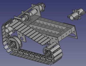
Gallery
Concept Design
2015 Build
Proof of Concept of MicroTrac Scalability - LifeTrac 7
The MicroTrac is overbuilt to 8000 lb of drive torque plus the ability to carry an extra 6000 lb of weight outside of its existing 2000 lb weight. With the structural Power Cube as the basis for other attachments, the MicroTrac can be scaled in size to build bulldozers by stacking 3 MictroTracs together for 24,000 lb of torque at the tracks. See initial testing of weight handling capacity, where the MicroTrac carries 6000 of dead weight, and is shown running in idle:
Hackaday Documentation
Go to Hackaday - [6]
Loader Arms
Here is a partial prototype of adding a Driver's Cab, second Power Cube, and loader arms to the base tracked platform consisting of tracks and power cube.
Modules
Development Template
The condition of satisfaction for torque was idle -
Working Document
Overview
The Bulldozer is a high-traction, earth-moving machine indispensible to building ponds, berms, or other earth-moving tasks such as building roads or clearing land. See Bulldozer Specification
Details
Most often, bulldozers are large and powerful tracked heavy equipment. The tracks give them excellent ground hold and mobility through very rough terrain. Wide tracks help distribute the bulldozer's weight over a large area (decreasing pressure), thus preventing it from sinking in sandy or muddy ground. Extra wide tracks are known as 'swamp tracks'. Bulldozers have excellent ground hold and a torque divider designed to convert the engine's power into improved dragging ability. The Caterpillar D9, for example, can easily tow tanks that weigh more than 70 tons. Because of these attributes, bulldozers are used to clear areas of obstacles, shrubbery, burnt vehicles, and remains of structures.
The GVCS variant is being pursued as a Tractor bladed retrofit with lower torque, and additional weight
Product Ecology
Made with
 Induction Furnace - Steel
 Tractor - Base
 CNC Torch Table - Parts
 Welder - Attachment
 Power Cube - Power
Creates
Components
- Hydraulics
- Blade
- Blade Lift
- Ripper
- Cab
- Tracks
Status
The Bulldozer is currently in the Research Phase of Product Development.
Videos
See Also
OSE Links
| GVCS Home List | ||
|---|---|---|
| Home | Research & Development | Bill of Materials | Manufacturing Instructions | User's Manual | User Reviews | File:GVCS Home List.png | |
The Open Source  Car is an automobile designed for transporting passengers.
Team Wikispeed
Joe Justice and Team Wikispeed are awesome and we're planning a formal partnership!
The instructions for copying Team Wikispeed's SGT01 car design are currently being built. You can find them here Wikispeed_SGT01
OSVehicle Tabby
The OSVehicle Tabby's chassis, suspension, ... can be ordered from their website (see also here). The vehicle can then be custom made by the person that ordered the parts.
Custom mini moke
A custom mini moke can be created for the purpose of creating a community of green mechanics which also organise races (on regular karting tracks). The mini moke design will form the "glue" to create this community due to the fact that unlike with regular karts, no trailer is needed to transport the racing vehicle (instead, the mini car can be driven itself to the track, and even also prove useful for day to day activities, meaning it isn't just an expense done for hobby purposes). The design would hence make the step towards engaging in this hobby smaller, and help convince more people into doing it.
Team Vélocar
Vélocar joined the OSE movement. Vélocar is now the official OSE microcar

Overview
The OS Car will be a lightweight and aerodynamic two passenger long range car that will be fueled with ethanol biodiesel. The current plan is for the car to have a reverse trike configuration: two front wheels and one rear wheel which is the only driven wheel. The two main benefits of the reverse trike design are lower cost and weight due to one less wheel, and lower wind drag due to the rain drop shape of the body. The construction of the car will be a steel space frame covered with non-structural polymer or composite panels. The proposed powertrain is a hybrid hydraulic system which includes a single cylinder engine that runs a hydraulic pump which directly powers a hydraulic wheel motor used to drive the car and which compresses a gas in an accumulator to store energy. Gas in the accumulator will also be compressed via regenerative braking when the hydraulic motor is run in reverse to slow the car down. Cost control and quick development will be maintained by using donor vehicle parts and off-the-shelf parts. Components that cannot be easily manufactured such as brake calipers, steering knuckles, and rims will be sourced from a donor vehicle and components such as instruments, wiring, and hydraulic components will be off-the-shelf components.
As the car design matures, some components from donor vehicles and off-the-shelf components can be replaced by scratch-built open source components. If desired, forks can be spawned from the original project for variants such a four or five passenger car, or perhaps a car with a hybrid electric powertrain.
Update - July, 2013 - See Yann Log
UELVEs MBC
The UELVEs MBC is a libre-licensed 100kg 2-passenger concept vehicle currently in development, with off-the-shelf downhill mountainbike parts, twin Sur-Ron eBike motors, and using 3D-printed space-frame nodes and fibre-reinforced pipes, with the GABoats (Geodesic Aerolite Boats) technique and materials for its outer skin. Anticipated top speed if the expected drag coefficient can be achieved: over 100mph. Fuel efficiency (again dependent on the Cd): around 90mpg at 100mph, and over 200mpg at 55mph.
Product Ecology
| From | Uses | Creates | Enables |
|---|---|---|---|
Components
|
Status
The Open Source Car is currently in the Research Phase of product development.
The Open Source Car in the media
The Open Source Car has been covered in the following online media sources
- Press Release OSE-Wikispeed Collaboration
- Car Technologies of the Future
- A Visit To the Open Source Ecology Project
- Open Source Ecology P2P Foundation
See Also
Link to CEB Press Build June 2015
The CEB Story 2012. from Open Source Ecology on Vimeo.
| GVCS Home List | ||
|---|---|---|
| Home | Research & Development | Bill of Materials | Manufacturing Instructions | User's Manual | User Reviews | File:GVCS Home List.png | |
Overview
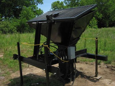
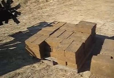
The Liberator is OSE's automatic, high throughput Compressed Earth Brick Press. It is named The Liberator because it is intended to free people from the single highest cost of living - housing. See Cost of Living.
The CEB is at product release status and is being actively manufactured at Factor e Farm. The presses was used heavily as a part of the Factor e Farm Infrastructure Buildout 2011. Builds using the OSE CEB ress continued with the Microhouse 1, Microhouse 2, Microhouse 3, and MicroHouse 4 built in 2014 - [7]. We have also built a utility room brick floor and an 8' wall section out of CEBs in the 2016 build of the Seed Eco-Home.
In 2020, we did a CEB Microhouse Build in Belize.
The bill of materials cost of the current, fully-automated machine is about $5000 US. See CEB Press#BOM.
The machine can also be made as a manually-controlled version with hydraulic valves. Other options are:
- small or large hopper
- with or without hopper shaker
- automatic controller at 6-10 bricks per minute, depending on power unit
We are currently selling the full machine without power unit for $10k FOB Kansas City, lead time 2 months. Email info at opensourceecology dot org.
- Price is FOB Kansas City, Missouri, USA, for a fully assembled machine, with quick couplers, ready to be plugged in to a power source. Price for other packing/crating options is extra.
- Delivery time: machines are produced during scheduled production runs, with 8 weeks lead time from submission of payment.
- Buyer is encouaraged to attend the build event - to learn how the machine is designed, built, and therefore, to learn about repair and modification. Basic instruction on using FreeCAD will be provided for viewing the CAD file. An operating and maintenance manual will be provided to the client. The buyer is encouraged to brind additional people to the build event to learn about the machine.
A tractor loader is used to provide approximately 2 cubic yards of soil per hour at at 6 block per minute pressing rate. A tractor loader is needed to keep up with the machine throughput. Approximately 3 people are required to keep up with the machine for stacking the block upon pallets. Approximately 30 people would be required to load the machine manually with shovels and buckets if no tractor loader were available. At the minimum, 4 people (1 tractor operator, 3 stackers) are required to produce palletized block on an all-day basis.
Specifications of the Standard Model
- Block is plain block, not interlocking. Please see discussion on Interlocking_bricks
- Version 17.08 is our most current model. See CEB Press Genealogy for past versions.
- Open source hardware, controller, and software (CC-BY-SA 4.0, GPLv3)
- Controller is fully automated for hands-off operation
- Does NOT come with a power source - it is powered by a hydraulic power source, such as by our Power Cube or a tractor hydraulic take-off.
- Full size bricks are 4"x6"x12", plain flat-faced bricks
- Brick height is adjustable from 2"-4"
- Brick dimensional variations: +/- 1/16". This assumes uniform soil. Soil uniformity will determine height uniformity of brick.
- The standard model guarantees 6 full-sized bricks per minute at 12.5 gallon per minute hydraulic flow. See Brick Pressing Calculations. Brick pressing rate will increase with a higher hydraulic flow, up to the maximum rated flow of the hydraulic solenoid. Hydraulic solenoid valve is rated for a maximum of 10 gpm fluid flow at 3000PSI.
- Cost of production for actual block ranges from 5 cents to 40 cents per block - depending on amount of cement used for stabilization (0-10%) and cost of labor (free to $25/hr). See Cost_of_CEB_Block
- Fuel consumption with Power Cube running at 12.5 gpm fluid flow - about 1 gallon per hour
- System hydraulic pressure - 2400 psi
- Comes with hydraulic quick couplers ready to be connected to a power source
- Weight - 1700 lb
- Moving: brick press is moved with forks. Footprint (with legs in the inner position) allows machine to be placed in the bed of a 3/4 ton pickup. It has adjustable legs for uneven terrain. Machine can be moved around on a trailer (not included)
- Material cost: $3000-$6500 depending on suppliers; manual machine (without hydraulic solenoid, machine costs $1000 less in materials. Production cost for a full kit: US$5000 above the bill of materials/supplies/consumables cost, paid by the buyer. Production currently occurs in Extreme Manufacturing Workshops - where the buyer is invited to the build so they understand how the machine is built - and is part of the buyer's Lifetime DIY Warranty. This warranty means that the user can maintain the machine for decades because they know how the machine is built, how it works, and how to source parts for the machine from local and online sources. This means that this is not a consumer machine, but a prosumer machine.
- 3'x6' grate for loading the machine with a tractor. Includes soil deflectors
Additional Power
The machine can be used to produce up to 10 blocks per minute with a larger power source. A larger secondary hydraulic cylinder must be used in that case. See CEB Press Log for developments.
BOM
See build BOM from 2017 at CEB_Press_v17.08#BOM
Versions
![]() Hint: For full project version history, see CEB Press Genealogy and CEB Press Controller Genealogy
Hint: For full project version history, see CEB Press Genealogy and CEB Press Controller Genealogy
Details
The CEB Press takes earth/dirt/soil and compresses it tightly to make solid blocks useful for building. Compressed earth blocks have many advantages as a building material: by making the building materials from the readily available dirt on the building site, they eliminate the need to transport bricks from elsewhere, reducing financial cost and environmental impact. Compressed earth blocks are very strong and insulate well against both heat and sound, making for very energy-efficient building (especially combined with the energy savings from not needing to transport them from offsite). Best of all, the material they use is already on-site and does not need to be purchased -- quite literally, dirt-cheap! See the wiki page on Compressed Earth Blocks and the CEB category for more details on building using CEBs.
The Liberator has been fully designed and tested by the Open Source Ecology team. Because the Liberator is an open source technology, you can freely download instructions to build your own from materials you can obtain yourself, or contact opensourceecology[at]gmail[dot]com to buy a kit or a finished machine.
Building a machine yourself might seem intimidating, but every step of the process is fully documented and the OSE community is available on our discussion forums if you need help, advice, or a little hand-holding.
Using the CEB Press, two people can build a 6 foot high (1.83m) round wall, 20 feet (6.1m) in diameter, 1 foot (30cm) thick, in one 8 hour day, though construction time will vary somewhat depending on preparation time, what equipment is available (tractor to prepare the ground and move the blocks where they need to go), the quality of the soil, and other factors. The bigger the block size, the faster a wall can be erected, but at the cost of heavier blocks that are more of a strain to work with. Blocks from The Liberator average 25 pounds (11.3kg).
See CEB Design for more information.
Product Ecology
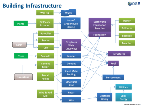
From
Uses
Creates
Enables
See Also
- CEB Press Genealogy
- Brick Pressing Calculations.
- Soil Testing
- more Soil Testing
- CEB Design
- Compressed Earth Blocks
- Cinva Ram
- CEB_FAQ
- CEB Press/Rollers
- CEB Press/ModularRollers
- Hablab
- Metric CEB Press
- Field Testing 2011
- CEB Press/Videos
| Cement Mixer | ||
|---|---|---|
| Home | Research & Development | Bill of Materials | Manufacturing Instructions | User's Manual | User Reviews | 
| |
Overview
A Cement Mixer (also commonly named a concrete mixer) is a device that homogeneously combines cement, aggregate such as sand or gravel, and water to form concrete. [1]
Detailed Description
A concrete mixer (also commonly called a cement mixer) is a device used to automate the preparation of cement by mixing it with other aggregates such as sand or gravel and water to form concrete. A typical concrete mixer uses a revolving drum in which the components are automatically mixed. The resulting mix is used as on of the most important elements on construction.
Concrete is used more than any other man-made material in the world. As a part of the GVCS, it unlocks a range of building techniques and methods, depending on characteristics of the environment and type of structure to be built.
Product Ecology
| From | Uses | Creates | Enables |
|---|---|---|---|
Components
|
OSE Project Status/Schedule
The concrete mixer is currently in development and is undergoing CAD stages of design. It is considered a priority for the 2011 Infrastructure Buildout, as a part of the GVCS Rollout
See Also
Links
| GVCS Home List | ||
|---|---|---|
| Home | Research & Development | Bill of Materials | Manufacturing Instructions | User's Manual | User Reviews | File:GVCS Home List.png | |
Overview
The Chipper Hammermill is a combination device that chips and hammers biomass into a uniform size useful for processing in the Pelletizer.
Details
Product Ecology
Made with
 Induction Furnace - Steel
 CNC Torch Table - Parts
Uses
 Power Cube - Power
 Hydraulic Motor - Actuation
Input
Creates
- Uniform Biomass for
 Pelletizer
 - Insulation for Hab Lab
See Product Ecologies for more information.
Components
- Frame
- Hopper
- Feeder
- Chipper
- Hammer
- Shaft
Status
The Hammermill is currently in the research phase of development.
See GVCS Rollout Plan for more information.
See Also
Basics
- A CNC mill used for PCB Milling
- Can't make as small of traces as a lithography+ethcing system, BUT it is far cheaper and easier to use (ie no chemical etchants or photoresists needed)
- Uses the D3D Univeral Axis
- D3D circuit mill - https://mi_shell.gitlab.io/models_online/ose_webgl/d3d_circuit_mill.html
Genealogy
- The CNC circuit mill took another turn in 2019 with the Open Source Microfactory STEAM Camp, where we built the D3D Universal 3D printer with a hole-drilling capacity for circuit boards.
- D3D CNC Circuit Mill - built in 2018 with the Universal Axis.
- We also built HydraFabber in 2014 - which used a low cost spindle. See John Log for pictures of the mill. This is prior to the Universal Axis, which was introduced in 2016. The spindle was built and run, but we did not mill any boards.
- Yoonseo Kang built a circuit mill while at OSE in 2012. See Yoonseo Log - as a power user, Yoonseo developed a lot of useful proofs of concept, such as the Cold Saw and Tooling Plate, among others. Specifically - v1 was built, and v2 was not. These were pre-Universal Axis.
3D Model
- You can rotate, zoom, and explode:
![]() Hint: July 2018 - OSE Germany is working on a version of their MPPT Solar Charge Controller which can be milled with the OSE D3D CNC Circuit Mill - https://github.com/LibreSolar/MPPT-Charger_20A/issues/28
Hint: July 2018 - OSE Germany is working on a version of their MPPT Solar Charge Controller which can be milled with the OSE D3D CNC Circuit Mill - https://github.com/LibreSolar/MPPT-Charger_20A/issues/28
Publication
Published in Inventions, http://mdpi.com/2411-5134/3/3/64
Preprint - https://www.preprints.org/manuscript/201808.0233/v1
Build Instructions
- Drill frame
- Do Cut List below - rods, belt
- Cut bed plate
- Assemble electronics mounting plate
- Assemble spindle in holder
- Test electronics - motion
- Test calibration code
- Run a milling job
Cut List
(400, 350, and 300 lengths would work)
- Belt - x - [2] 29"
- Belt - y - [2] 33"
- Belt - z - [2] 23"
- Rods - x - [4] 14"- = 56"
- Rods - y - [4] 16"- = 64"
- Rods - z - [4] 11" = 44"
- Frame if welded from flats - [24] 1/8"x1"x15" flats -
- Electronics mounting panel - 1/10" plexiglass - 8"x16"
Rods if Using 6' Stock
Try 1
- If use 6 foot stock- 72" - 4x11=44 + 28 = 72.
- 4x16 = 64 (8 left over). It's useful to rework design to allow for 8" rod on Z
- 2x14 = 28 (44 left over)
- 3 rods needed for 162" = 13.5'
Try 2
- 4x14 + 16 => perfect.
- 3x16 + 2x11 = 70 for 2" left over- great.
- 2x11 = 22 with 50 left over. Nice.
Continuing:
- 3x16= 2" left over from last one.
- 4x14 + 16 => perfect
- 1x16+4x11 = 60 - 12 left over.
Italic text
July 2017
Comparison to Industry Standards
Notes: precision is not defined here. If it is positioning accuracy, Othermill appears to be 0.003 (see D3D_CNC_Circuit_Mill#Industry Standards.
BOM
Other Supplies
Single Sided Copper Clad Laminate PCB Circuit Board 4X3 (50pcs) Paramount CCL Link: http://a.co/3YcKSBe
Xuchuan 10Pcs PCB Print Circuit Board Carbide Micro Drill Bits 0.3-1.2mm Xuchuan Link: http://a.co/0KviIvf
JIUWU 1.0mm Tungsten Steel Carbide PCB CNC End Mill Engraving Bits Milling Machine Pack of 10 by JIUWU Link: http://a.co/1CL0H32
You can try these tools out - they are inexpensive and may yield good results for milling traces. But if you run into issues, the tools are likely chipping Autek 10x Titanium Coated Carbide PCB Engraving CNC Bit Router Tool 30 Degree 0.1mm Tip(J3.3001Tix10) by Autek Link: http://a.co/6UR8F9T
Instead it may be good to opt for higher quality milling tools. They should last a good long while:
	Universal Milling Tools
	100% Carbide universal milling tool for milling printed circuit board isolation tracks. V-shaped profile for variable milling width. 1.42" (36 mm) overall length.
https://www.lpkfusa.com/Store/pages/ProductDetail.aspx?cat=11%2f42&cid=42&pid=30
All Industrial Tool Supply TR72020 Dial Indicator (Magnetic Base and Point Precision Inspection Set), 1 Pack by All Industrial Tool Supply Link: http://a.co/5EgkHa0
Software: See this link - it has all of the software we used and then some: http://opencircuitinstitute.org/content/software
Additionally here is my web-based leveling utility: http://voltfolio.com/utilities/levelgcode.html
https://www.lpkfusa.com/Store/pages/ProductDetail.aspx?cat=11%2f38&cid=38&pid=76
Sorry I must make one amendment - I linked the incorrect milling tools from LPKF. Here are the correct ones:
https://www.lpkfusa.com/Store/pages/ProductDetail.aspx?cat=11%2f38&cid=38&pid=76
vBOM
Visual BOM:
Calculations
Sources
- File:Backlash Pattern.odg - editable drawing of backlash pattern.
Electronics
Source
- Diagram in Libre Office - File:D3D Circuit Diagram.odg
Photo Album
- On google photos - [8]
Videos
- Mill Experiment - Backlash Compensation Stress Test - [9]
- Leveled circuit - holder slides at the end - [10]
- Mill Experiment - Large Leveled Circuit Take 2 - [11]
- Auto Probing Experiment - [12]
- Stepper driver breakout board - [13]
Workshop Preparation
Development Template
Burndown
Feb 2018 Update
September 2017 Update
Development Pictures
The disassembled axes required to convert the D3D printer to the circuit board mill
These are the required additional parts to transition from the 3D printer to the circuit board mill
The complete set of axes for the D3D circuit mill
Working Document
Design
Data Collection
CAD files
- Assembly: File:D3D Circuit Mill.fcstd
Simplified Files
Assembly: File:D3D Circuit Mill.fcstd
D3D frame 16": File:D3D frame assembled 16 inch.FCStd
Single x axis: File:D3D Circuit Mill X Axis.fcstd
Single y axis: File:D3D Circuit Mill Y Axis.fcstd
Single z axis: File:D3D Circuit Mill Z Axis.fcstd
spindle motor: File:T-king spindlemotor.fcstd
Spindle Motor Mount: File:D3D Circuit Mill Motor Mount.fcstd
PCB holder: File:PCBholder simplified.FCStd
Accurate Files
3x End Stop interface: File:D3D End stop interface.fcstd
16x carriage piece: [[1]]
16x idler piece short: [[2]]
12x motor piece: [[3]]
2x Spindle Motor Mount: File:D3D Circuit Mill Motor Mount.fcstd
PCB holder: [[4]] and File:D3dcnccm PCB holder.stl
List of Files
- Assembly: File:D3D Circuit Mill.fcstd
- Frame 16" assembled: File:Full Frame 16in.FCStd
- Single 16" frame: File:Single Frame 16in.fcstd
- Single x axis: File:D3D Circuit Mill X Axis.fcstd
- Single y axis: File:D3D Circuit Mill Y Axis.fcstd
- Single z axis: File:D3D Circuit Mill Z Axis.fcstd
- Spindle Motor: File:T-king spindlemotor.fcstd
- Spindle Motor Mount: File:D3D Circuit Mill Motor Mount.fcstd. STL - File:D3D Circuit Mill Motor Mount.stl
- PCB Holder: File:D3dcnccm PCB holder.stl File:PCBholder simplified.FCStd
Design Notes
Note on CAD Procedure and Organization:
- Draw a frame piece, and create a complete frame made of 6 of these pieces.
- Save file: File:D3D 13" Frame.fcstd
- Begin the design by downloading the X axis - File:D3D 16 Sub-assembly X Axis.fcstd
- Correct the length of the axis to 11" length (for 13" frame - 1" shorter on each side to accommodate mounting on the Y axes). Rotate the axis such that the orientation - when looking according to the Viewing Direction and XYZ axis orientation of Slide 1 in Working Document - is that the motor is on the left side of the axis (note that the orientation shown in First Slide in the Working Document has the motor on the right hand side, which is not correct).
- Save the file as File:D3D Circuit Mill X Axis.fcstd once the length is 11" and orientation is correct. This will be the file you can use later for the x axis (2 of them) to merge into the final assembly - with the second x axis being a mirror image.
- Now create the Y axis according to the orientation convention of the First Slide in the Working Document. This axis should be 13" long.
- Save the y axis file as File:D3D Circuit Mill Y Axis.fcstd.
- Now create the Z axis as in the working document. This axis can be 8" long - as we don't need a lot of z travel.
- Save the Z axis file as File:D3D Circuit Mill Z Axis.fcstd.
- Import the
Industry Standards
- Toner Transfer gets reliable traces down to 0.15 mm, D3D CNC circuit mill works to 0.5 mm traces. [[14]. Disadvantage: a mill can do your holes and cut out your circuit board as well. Advantage - smaller features are possible.
- Othermill - 0.003 mm positioning, with minimum mill bit of 0.25 mm - [15]. Positioning accuracy is not the limiting factor for features - but mill bit size. Minimum size is the same for D3D and Othermill (0.25 mm).
- [The Ant PCB Maker]
- Hackaday projects - [16]
- Not open source - LilCNC - [17]. Uses Easel online 2D design software.
Existing Open Source Designs
Curriculum
- Working doc - [18]
See Also
- PCB Milling with Marlin
- Universal CNC Axis
- Open Source Digital Fabrication Construction Set
- Open Source Electronics Construction Set
Useful Links
- Tom's Guide 2018 discussing inferiority of mill conversions - [19]
![]() Hint: Current work uses the Universal Axis as part of a precision motion ecocystem. See current work at D3D CNC Torch Table
Hint: Current work uses the Universal Axis as part of a precision motion ecocystem. See current work at D3D CNC Torch Table
Overview
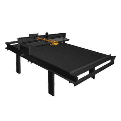
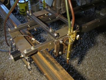
The CNC Torch Table (aka RepTab) is an enabling machine for any workshop. This machine enables creation of custom parts for fabrication or replacement of broken components. The CNC Torch/Plasma Table development is rebooting and building on some of the later versions, but starting with the replication of Koruza's Good Enough CNC Plasma Table. One the integrated designs is to go towards gas versus plasma, because of the dependencies of a plasma cutter and other devices that have not been fully open source. As well as the availability of gas production being a valuable option. The Version 3 iteration expects to build, source, and improve designs toward a 100% open source project and parts. The power supply, height controller, torch, and plasma cutter are items needing to be developed. In progress, the need for on-demand materials and supplies can be met with a functional and accurate CNC Torch/Plasma Table that will reduce manufacturing time and increase capacity. The Koruza Project does not a have table, therefore, building on previous versions maybe a possibility.
2021
Ken Makunga implemented height control and auto gas control using Marlin 3D printer firmware during Summer X
2019 Update
- Working on CNC Torch Table Height Controller
2016 Update
During the course of 2014/2015 workshops of metal fabrication, the CNC Torch Table/Plasma Table is essential for future builds. The MicroTractor and the World's First Open Source Bulldozer can be built with general metal working toolings, however, the CNC Torch Table is a major manufacturing component of the GCVS. Tom Griffing and Jonathan Kocurek find it a useful effort to focus on the CNC Torch Table for PowerCube replications and parts manufacturing. Marcin's introduction with the Koruza project is a feasible option, however, Marcin's concerns are that some propriety parts exists that will need to be open source and developed. Such as the height controller and power supply. Tentative plans and efforts to grow the CNC Torch/Plasma Table Team are forming for 2016.
2014 Team Goals
Current team goals as of June 5 2014 for the end of June 2014.
- Have the torch cutting steel, up to 1" thick, to a tolerance of 1/16" over 10 inches on all dimensions, and within 1/16 of a straight line re the waviness of the line. It is ok if it takes some manual intervention, or hand holding.
- The machine should be reasonably durable and not finicky or prone to breakage, or absurdly high wear and tear. For example, the wiring is currently prone to breakage. Also the arduino on the z control would probably stop working pretty fast from the stuff splattering on it.
This entails meeting milestone 1 in the torch table prototype 2 requirements document (see dev board through dozuki, overall module, requirements document).
- for the short term, make sure the documentation is at the point that someone can easily step in to Anthony's role in getting things working, and to operate the table for cutting.
- record why we made the system the way we have so far, rather than some other way. This is important to avoid the need to go over the same ground too many times.
2016 Team Goals
- Using 3D Printer Construction Set instance for xyz drive.
- Off-shelf height controller tested, then replaced with open source version
- Open source version - done by a design challenge, such as heroX or simple crowd platform
Versions
Details
The CNC Torch Table allows workshops to create replacement parts on the fly for many of the components used in the GVCS. Additionally, the Torch Table gives workshops the ability to create many of the custom components used in the GVCS Machines. Many parts that make up the 50 GVCS Tools can be cut on the CNC Torch Table, making this machine valuable for replication.
Documentation
Much of the current documentation and raw data concerning
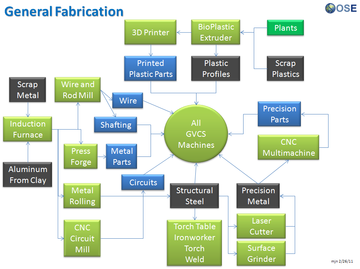
Product Ecology
Made with
 Multimachine - Precision Guides, bearings
 Ironworker
Creates
See Product Ecologies for more information.
See Also
- CNC Torch Table Crash Course
- Research & Development
- Bill of Materials
- Manufacturing Instructions
- User's Manual
- CNC Torch Table Github Repo
- OSE CNC Torch Table Development Google Group / Mailing List
- CNC Torch and Router Table on Dozuki
| GVCS Home List | ||
|---|---|---|
| Home | Research & Development | Bill of Materials | Manufacturing Instructions | User's Manual | User Reviews | File:GVCS Home List.png | |
Overview
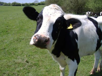
The Dairy Milker yields milk and dairy products from dairy cows.
The pulsator can use Solenoid Driver
Detailed Description
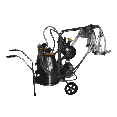
The dairy milker is comprised of 4 teatcups that attach onto the teats of the dairy cow. These teatcups connect via short milk tubes and short pulsation tubes to a claw (connection component that links the teatcups to the rest of the dairy milker). The claw is connected via a long milk tube and a long pulsation tube to the milkline (collection bucket), from which the collected milk is transported via airflow and pump to a bulk tank (central storage vat). The dairy milker yields milk from the teats of a cow by applying a continuous vacuum, thereby creating a pressure difference across the teat canal. Because the vacuum causes teat tissue congestion (problematic accumulation of blood and other fluids), air is pulsated to the teatcup liners at pre-determined intervals to ease tissue congestion.
Solution Statement
The agricultural pathway for dairy products necessitate the production of milk, for which the dairy milker provides an automated means to do so.
Product Ecology
Made with
 Induction Furnace - Steel
 Welder
 Plasma Cutter
To be used in conjunction with:
- Cow - Milk
- Pasteurizer (To increase shelf life and reduce the number of viable pathogens-Wikipedia page)
Creates
The dairy milker fulfills the role of producing milk from cows through automation.
Components
The major components of the dairy milker include:
- Claw - the intermediary part that connects the short milk and pulsation tubes from the teatcups to the long milk and pulsation tubes going to the collection bucket.
- Teatcups - the direct contact parts that gently clasp onto the teats of a dairy cow so that the applied vacuum yields milk.
- Collection Bucket - The minor receiver of extracted milk that connects to the bulk tank.
- Bulk Tank - The major receiver of extracted milk that can connect to multiple collection buckets.
- Pump and Airflow Circuit - the set of parts that create a pressure difference between the collection bucket and the bulk tank, thereby channelling extracted milk from the collection bucket to the bulk tank.
- Vacuum and Pulsation Circuit - the set of parts that produce the vacuum and air pulsation intervals for milk extraction and teat tissue relief, respectively.
Status
The Dairy Milker is currently in the research phase.
Videos
See Also
| GVCS Home List | ||
|---|---|---|
| Home | Research & Development | Bill of Materials | Manufacturing Instructions | User's Manual | User Reviews | File:GVCS Home List.png | |
Overview
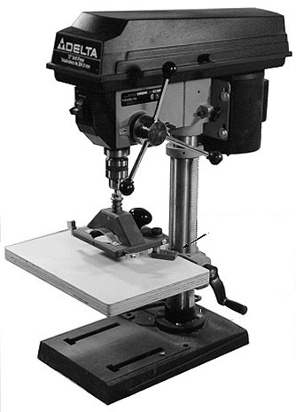
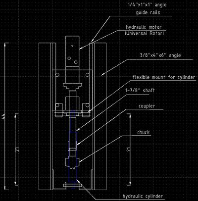
A drill press (also known as pedestal drill, pillar drill, or bench drill) is a fixed style of drill that may be mounted on a stand or bolted to the floor or workbench. A drill press consists of a base, column (or pillar), table, spindle (or quill), and drill head, usually driven by an induction motor. The head has a set of handles (usually 3) radiating from a central hub that, when turned, move the spindle and chuck vertically, parallel to the axis of the column. The table can be adjusted vertically and is generally moved by a rack and pinion; however, some older models rely on the operator to lift and reclamp the table in position. The table may also be offset from the spindle's axis and in some cases rotated to a position perpendicular to the column.
Details
Status
The Drill Press is currently in the prototype phase of design.
See Also
| GVCS Home List | ||
|---|---|---|
| Home | Research & Development | Bill of Materials | Manufacturing Instructions | User's Manual | User Reviews | File:GVCS Home List.png | |
see also: Hydraulic Motor
Overview
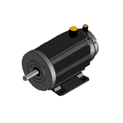
The Electric Motor serves the function of converting electrical energy into mechanical energy and vice-versa.
Detailed Description
Most electric motors operate through the interaction of magnetic fields and current-carrying conductors to generate force. The reverse process, producing electrical energy from mechanical energy, is done by generators such as an alternator or a dynamo; some electric motors can also be used as generators.
The ideal GVCS motor is one that meets OSE Spec for appropriate scale and ease of fabrication.
While many heavy-duty GVCS technologies are powered by Hydraulic Motors, many of the smaller, more precision actuation is left to Electrical Motors.
Product Ecology
| From | Uses | Creates | Enables |
|---|---|---|---|
Components
|
Status
The Electric Motor Generator is currently in the Research Phase of product design.
See Also
- Dirk 3D Printed Electric Motor Development
- Stepper Motor
- Motor selection
- Appropedia: Comparison of electrical motors - types and applications, 3D models.
- Wikipedia: Electric Motor
- Wikipedia: Electrical Generator
- Electricity
Gasifier Build Workshop in 2015 with gasoline engine Power Cube running on charcoal. See more info at Gasifier_Construction_Set_Workshop:
![]() Hint: OSE's gasifier build from 2015 is at Gasifier_3D_CAD. This is worth developing to a product.
Hint: OSE's gasifier build from 2015 is at Gasifier_3D_CAD. This is worth developing to a product.
| GVCS Home List | ||
|---|---|---|
| Home | Research & Development | Bill of Materials | Manufacturing Instructions | User's Manual | User Reviews | File:GVCS Home List.png | |
See Developent Spreadsheet for Gasifier Burner
Overview
The Gasifier Burner converts biomass fuel into power and useful chemicals.
See Gasifier Development Template for 2015 Development.
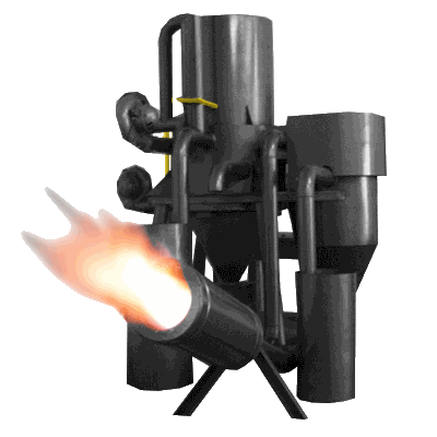
Details
This is achieved by reacting the material at high temperatures (>700°C), without combustion, with a controlled amount of oxygen and/or steam, breaking down the biomass into carbon monoxide, hydrogen, carbon dioxide and methane. The resulting gas mixture is a fuel called syngas. If Air is used in place of oxygen the gas also contains inert nitrogen and is called producer gas.
Product Ecology
| From | Uses | Creates | Enables |
|---|---|---|---|
|
Components
|
Status
The gasifier burner is currently in the Research phase of development.
Join the conversation here: https://groups.google.com/forum/#!forum/ose-gasifier-burner-development
See Also
| GVCS Home List | ||
|---|---|---|
| Home | Research & Development | Bill of Materials | Manufacturing Instructions | User's Manual | User Reviews | File:GVCS Home List.png | |
Overview
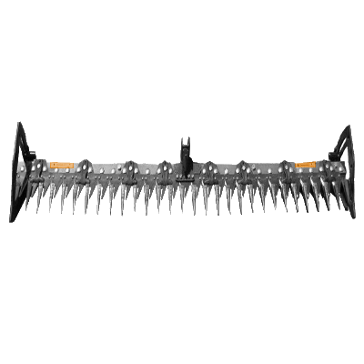
A hay cutter is a device that cuts grass, hay, straw, or other light biomass. It is part of haying equipment, haybines, silage equipment, mowers, and agricultural combines.
This should really be called a mower. More specifically, a reciprocating mower, sickle mower, or finger-bar mower. A "hay cutter" can be mistaken for something more like a wood chipper that chews up biomass and spits it out a chute.
Details
A cutter has a number of moving parts and is subject to failure. Open source, modular hay cutters solve the need for easy self-maintenance and adaptation to many devices, from combines to balers, reducing infrastructure costs. The goal is a machine that fully meets OSE Spec
Product Ecology
Made with
 Induction Furnace - Steel
 CNC Torch Table - Cut parts
Uses
Creates
- Hay
Components
- QA Plate
- Mounting Frame
- Blades
- Hinge
Study of Industry Standards
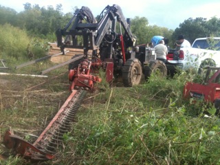
OSE hay cutter is studying the industry standards with this hydraulic-retrofit of a hay cutter:
See Also
| GVCS Home List | ||
|---|---|---|
| Home | Research & Development | Bill of Materials | Manufacturing Instructions | User's Manual | User Reviews | File:GVCS Home List.png | |
Overview
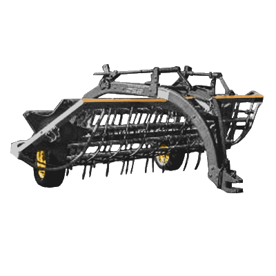
The Hay Rake is an agricultural rake used to collect cut hay or straw into windrows for later collection (e.g. by a baler or a loader wagon). It is also designed to fluff up the hay and turn it over so that it may dry. It is also used in the evening to protect the hay of the dew. The next day a tedder is used to spread it again, so that the hay dries more quickly.
Details
Product Ecology
Made with
 Induction Furnace - Steel
 CNC Torch Table - Parts
Uses
Works With
Creates
See Product Ecologies for more information.
Components
- QA Plate
- Frame
- Rake
Status
The Hay Rake is currently in the Research phase of product development.
See Also
| Hydraulic Motor | ||
|---|---|---|
| Home | Research & Development | Bill of Materials | Manufacturing Instructions | User's Manual | User Reviews | 
| |
Overview
A hydraulic motor is a mechanical actuator that converts hydraulic pressure and flow into torque and rotation.
Detailed Description
In the GVCS, the hydraulic motor forms the energy backbone powering much of the equipment. Hydraulic power offers numerous advantages that make it an attractive aspect in helping machine meet OSE Spec
See Power Cube, CEB Press, and Tractor for implementation examples.
Product Ecology
| From | Uses | Creates | Enables |
|---|---|---|---|
|
Components
|
|
Status
The Hydraulic Motor is currently in the research phases and is dependant on product release of precision equipment provided by Multimachine.
See Also
| GVCS Home List | ||
|---|---|---|
| Home | Research & Development | Bill of Materials | Manufacturing Instructions | User's Manual | User Reviews | File:GVCS Home List.png | |
Main > Digital Fabrication > RepLab Tools > Induction furnace
Overview
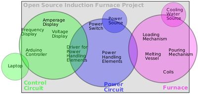
An induction furnace is composed of an induction coil, alternating current power supply, and electrically conductive workpiece.
The 'primary' coil induces current in the 'secondary' workpiece through electromagnetism.
This current is converted to heat at a rate of VI=I2R.
The magnetic field does not induce a uniform current in a solid rod, but reduces and lags in phase towards the center. A parameter called reference depth d is used to determine the length at which the field strength is reduced to 1/e (37% compared to the surface).
Copper is often chosen as a material for the coil due to being a common metal with the lowest resistance.
Requirements
- Meets OSE Specifications
- Modular in power units of 5 or 10 kW
- Microcontroller-driven - ideally an Arduino brain with power elements
Details
The advantage of the induction furnace is a clean, energy-efficient and well-controllable melting process compared to most other means of metal melting. Most modern foundries use this type of furnace and now also more iron foundries are replacing cupolas with induction furnaces to melt cast iron, as the former emit lots of dust and other pollutants. Induction furnace capacities range from less than one kilogram to one hundred tonnes capacity and are used to melt iron and steel, copper, aluminium and precious metals. Since no arc or combustion is used, the temperature of the material is no higher than required to melt it; this can prevent loss of valuable alloying elements.[1] The one major drawback to induction furnace usage in a foundry is the lack of refining capacity; charge materials must be clean of oxidation products and of a known composition and some alloying elements may be lost due to oxidation (and must be re-added to the melt).
Operating frequencies range from utility frequency (50 or 60 Hz) to 400 kHz or higher, usually depending on the material being melted, the capacity (volume) of the furnace and the melting speed required. Generally, the smaller the volume of the melts, the higher the frequency of the furnace used; this is due to the skin depth which is a measure of the distance an alternating current can penetrate beneath the surface of a conductor. For the same conductivity, the higher frequencies have a shallow skin depth - that is less penetration into the melt. Lower frequencies can generate stirring or turbulence in the metal. A preheated, 1-tonne furnace melting iron can melt cold charge to tapping readiness within an hour. Power supplies range from 10 kW to 15 MW, with melt sizes of 20 kg to 30 tonne of metal respectively.
An operating induction furnace usually emits a hum or whine (due to magnetostriction), the pitch of which can be used by operators to identify whether the furnace is operating correctly or at what power level.
Development Notes
Read a commercial description of an induction furnace from Voltamptransformers
Read about 3-phase electrical power at its wikipage
Read about 3-phase electrical standards in north America at control.com forums
Product Ecology
Uses
 Universal Power Supply - Power
Creates
See Product Ecologies for more information.
Components
- Induction Furnace Circuit
- Heat Dissipation System
- Coil
- Melt Chamber
- Feeder
- Crucible
Status
The Induction Furnace is currently in the research phase of product development.
Internal Links
External Links
- Wikipedia: Induction Furnace
- Wikipedia: Investment Casting
- Molten Oxide Electrolysis - carbon free process that goes directly from ore to pure metal with pure oxygen as a byproduct
- NASA's page on MOE
- Youtube: Better Metal from Bill Gates youtube channel
- Youtube: Donald Sadoway at EmTech MENA 2019: Steel Production without Co2 Emissions
- An Open Source Design for a 3kw Induction Heater
| GVCS Home List | ||
|---|---|---|
| Home | Research & Development | Bill of Materials | Manufacturing Instructions | User's Manual | User Reviews | File:GVCS Home List.png | |
Overview
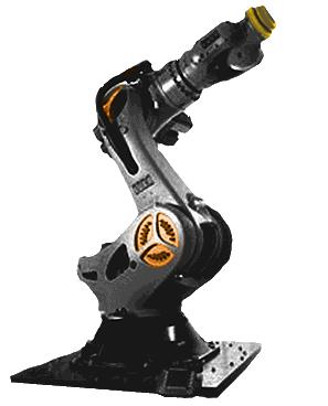
The industrial robot is an automated machine that perform a wide variety of functions, (including welding, assembly, and CAM, etc...), all depending on which tools its hand is equipped with.
This is the kind of thing you can do with a top-of-the-line industrial robot.
Detailed Description
The industrial robot is a rotating multi-axis machine that can hold various modules (called end-effectors) for performing different tasks such as welding and cutting. These tasks can be done in repetition (through proper "teaching") and with precision (based on the robot's repeatability, which is a measure of how far the robot deviates from a certain position when going there multiple times). The volume in which the robotic arm can travel is called the working envelope (rear of robot is typically restricted), and the axes of rotation are called degrees of freedom (6 or more for higher-end flexibility). A versatile industrial robot can significantly improve the accuracy, precision, and completion times of multiple production tasks while significantly reducing the need for operator involvement.
The industrial robot is task versatile, multi-way programmable, repeatably accurate, and modular with scalable reach and payload. The industrial robot serves a universal function mimicking a human arm, so can fill in (after being programmed) for any repetitive operation not better done by humans; other times, the industrial robot can be directly operator-controlled to act as a mega-arm machine where the high reach, payload, and working envelope are advantaged.
Product Ecology
| From | Uses | Creates | Enables |
|---|---|---|---|
|
Components |
Status
The Industrial Robot is currently entering the prototype phase of production.
See Also
Useful Links
- Wikipedia: Industrial Robot
- Open source 4 axis robot
- A Video by the Youtube Channel "Skyentific" on humanoid robotic arms
| GVCS Home List | ||
|---|---|---|
| Home | Research & Development | Bill of Materials | Manufacturing Instructions | User's Manual | User Reviews | File:GVCS Home List.png | |
Overview
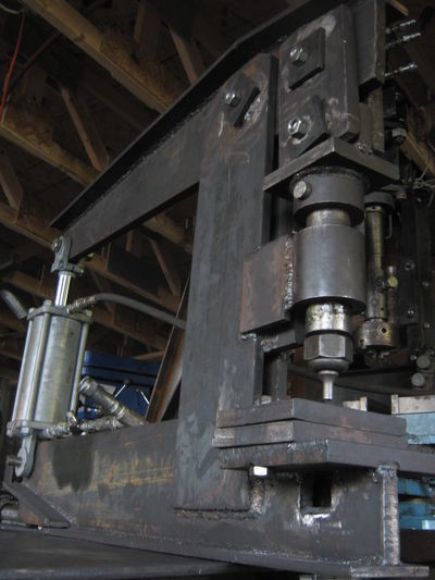
Ironworker machines can shear, punch holes and notch in steel plates.
Versions
See Ironworker Genealogy.
Details
An Ironworker is a fundamental machine for working with many and is the backbone of many fabrication workshops. It generates tremendous force using hydraulic systems and mechanical leverage.
Product Ecology
Uses
 Induction Furnace Steel
 Welder parts
Creates
See Product Ecologies for more information.
See Also
| GVCS Home List | ||
|---|---|---|
| Home | Research & Development | Bill of Materials | Manufacturing Instructions | User's Manual | User Reviews | File:GVCS Home List.png | |
Overview
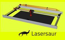
A laser cutter enables CNC cutting and engraving of metal, wood, and other materials. Laser cutting works by directing the output of a high-power laser, by computer, at the material to be cut. The material then either melts, burns, vaporizes away, or is blown away by a jet of gas, leaving an edge with a high-quality surface finish. Industrial laser cutters are used to cut flat-sheet material as well as structural and piping materials.
Details
lasersaur from stefanix on Vimeo.
Product Ecology
Uses
 Induction Furnace - Structural Metal
 Multimachine -
 CNC Circuit Mill - Controller
 Electric Motor Generator
- Power
Creates
 3D Printer - Structural
Components
See Product Ecologies for more information.
Status
The Laser Cutter is currently in the Development phase by Lasersaur, and will be a part of the GVCS when complete.
Videos
See Also
Usefull Links
| GVCS Home List | ||
|---|---|---|
| Home | Research & Development | Bill of Materials | Manufacturing Instructions | User's Manual | User Reviews | File:GVCS Home List.png | |
Overview
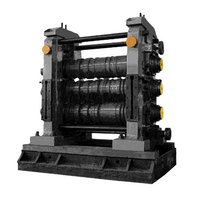
The metal roller sends sheet metal and plate through gaps between cylinders to roll-bend them; this operation is used for producing cylindrical or conical components as well as wiring cylindrical edges.
This roll-bending operation ability is particularly useful for producing standard shapes of metal that would be time-consuming or impossible to form otherwise.
Description
Metal rolling is a centralized industrial process that is done in large-scale (kiloton per day) steel mills. We aim to open-source this technology for use in small-scale (ton per day) flexible fabrication facilities which allow local communities to produce virgin metal from scrap feedstocks.
Description
One type of metal roller uses a pinch rolling operations (lightly grips and moves sheet metal through the machine with a "free" roller to "set" the required bend radius) and pyramid rolling operations (moves plate metal through the machine to "set" the required bend radius). A hydraulically power-driven universal metal roller can be used for all required roll-bending operations.
Solution Statement
The metal roller allows the operator to perform roll-bending operations with ease.
Product Ecology
Made with
Uses
 Power Cube - Power
 Induction Furnace - Steel
Creates
- Rolled Steel
See Product Ecology for more information.
Components
The principal elements of the metal roller include:
- Frame: the ground-supported structure upon which the rest of the metal roller lies
- Couplers: the mechanisms that convert rotary motion from the hydraulic motor to the cylinders
- Hydraulic Circuit: the set of components that powers the hydraulic motor by sending pressurized fluid through its ports, hence producing rotary motion at the motor shaft
- Adjusters: the mechanisms that allow cylinder movement for different placement configurations on the plane perpendicular to the axis of rotation
- Cylinders: the components that make actual contact with the workpiece for roll-bending.
Status
The Metal Roller is currently in the research phase of development. Prototyping is planned for after product release of the Induction Furnace.
See Also
| GVCS Home List | ||
|---|---|---|
| Home | Research & Development | Bill of Materials | Manufacturing Instructions | User's Manual | User Reviews | File:GVCS Home List.png | |
Overview
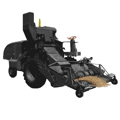
Agricultural Microcombine (Combine) - a combine is a complex device that cuts, threshes, and winnows grains and field crops of all sorts.
Details
Modern combines are huge devices today, and a smaller one is desirable for a small farm. This is not to say that this design should not be scaleable to larger size, as required to feed larger populations effectively. We propose a hybrid combine, with all parts driven by separate, infinitely speed controllable motors. This eliminates all pulleys and complexity of a single power source powering the entire modern combine. The key here is availability of cost-effective motors and controls, where today, motor controls are prohibitively expensive for such a proposition. OS changes this. With a microcombine under the control of the operator, expensive maintenance is avoided, and full food sufficiency becomes feasible on the tens-of-acres scale.
| From | Uses | Creates | Enables |
|---|---|---|---|
|
Components |
Status
Current work includes getting information from grain and bean farmers about their needs for a microcombine, the operation modes they'd like, etc. and surveying any commercial equipment available that is similar in scope/scale.
See Also
| GVCS Home List | ||
|---|---|---|
| Home | Research & Development | Bill of Materials | Manufacturing Instructions | User's Manual | User Reviews | File:GVCS Home List.png | |
![]() Hint: Latest version is MicroTrac_v17.10
Hint: Latest version is MicroTrac_v17.10
MicroTrac Geneaology
Working Model, 5/2013
April 17 2013
Corners for structural tubing
Corner inserts are one possibility for the Power Cube and for connecting tubular steel members. They would make better use of space that is currently used with the "layering" of tubes in current designs.
Mention was made that adding corners would weaken the overall design, but this has not been proven. A structural analysis would be necessary to find out for sure.
Here is an image of a possible corner: File:PC7s-frame-with-corners.png
Here is the Sketchup drawing: File:PC7s-frame-with-corners.skp Frame with corners
Overview
MicroTrac is a small scale, walk/ride-behind version of LifeTrac suited for construction, agriculture, and general home and garden maintenance.
Product Ecology
Made with
Equips
Components
Status
The Microtractor is currently in the Prototype stage of Product Development. Later prototypes aim to integrate lessons learned from LifeTrac development.
See GVCS Rollout for more information.
See Also
| GVCS Home List | ||
|---|---|---|
| Home | Research & Development | Bill of Materials | Manufacturing Instructions | User's Manual | User Reviews | File:GVCS Home List.png | |
![]() Hint: 2018 Update: see current work at D3D CNC Circuit Mill
Hint: 2018 Update: see current work at D3D CNC Circuit Mill
Links
Introduction
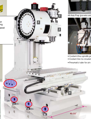
CNC Bed Mill with ATC
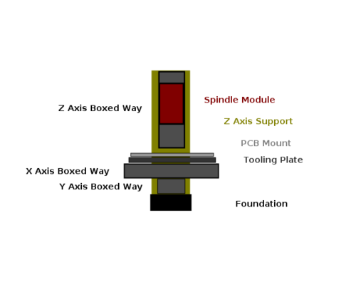
Notice how the following commercial vertical machining center connects the Z axis support frame to the Y axis frame, as well as how the Y axis frame rests on the table.
Mechanical Assembly Concept
Product Ecology
| From | Uses | Creates | Enables |
|---|---|---|---|
|
Components |
Rotary Module
Linear Guide
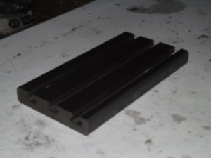
Tooling Plate and Accessories
Electronics Assembly
Software Toolchain
EDA (Electronic Design Automation)
Old Info
Internal Links
- D3D CNC Circuit Mill
- D3D 3 Axis CNC Mill
- Open Source Robotic Arm CNC Mill
- Precision Machining Construction Set
- 2" Universal Axis
External Links
- Open Source Machine Tools - spinoff of Multimachine website - [20]
- 5 ton CNC machine center with ATC- [21]
- CNC Programming and Machining manual on Scribd - [22]
- A Video by the YouTube Channel "Ivan Miranda" Titled "3D Printed CNC Knee Mill From Scratch
- The Design Files (20 USD but unclear on liscencing)
- Using cement inside 3D prints - Chris Borge - https://www.youtube.com/watch?v=L8t82OQXefM
| GVCS Home List | ||
|---|---|---|
| Home | Research & Development | Bill of Materials | Manufacturing Instructions | User's Manual | User Reviews | File:GVCS Home List.png | |
Overview
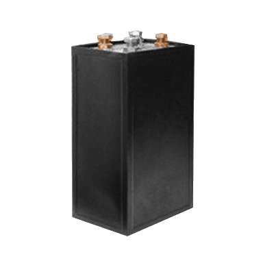
The Nickel Iron Battery is the only known lifetime design battery. These last 100 years, such as the Edison batteries unearthed after a century that work like new. Thus, it is the primary electrical energy storage device for the GVCS, outside of indirect sources such as Compressed Air Energy Storage, water Gravity Storage, and storage of energy via Hydrogen Production.
Advantages
- Theoretically unlimited lifetime: Long lifetime of 8-10 years - when you don't throw out the battery - just replace the electrolyte. [23]
- About X = $1000/kW - but unlimited life means that the full-cost accounted cost means that the cost is really X/N - where N is a number that you choose. Think of this - the core lives for ever - you replace the casing and electrolyte.
- Open source design of electrodes
- Cells can be made to any Ahr rating
- Nickel and iron obtained from scrap stream, reprocessed via Induction Furnace
- Completely closed loop material cycle ecology
- Max discharge/charge = C/2. Optimal charge/discharge - C/4. [24]
- Vidoe showing build of a simple cell - [25]
- Discharge at 1C rate appears to get 70% of battery capacity? Not likely, it must be more like time -
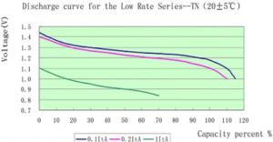 . Source - [26]
Disadvantages
- The historical NiFe technology’s notable limitations include low specific energy,
low power, low charge retention and poor low temperature performance along with being high cost1 and is still in limited mass production throughout the world today for specific applications. NiFe battery chemistry is known for its robustness, extreme shelf and cycle life. The historical NiFe technology that was most robust to abuse also had limitations in being heavy, low power, low charge retention and poor low temperature performance along with being high cost. Thus, over the years, other nickel battery technologies (e.g., NiCd, NiMH, NiZn, and NiH2) have displaced NiFe in many applications. [27]. This paper discusses the 'improved' Encell cell with much shorter lifetime.
- OSE Assessment:
- Low specific energy - still perfect for stationary applications of renewable energy
- Low power - in a renewable energy scenario, large loads are run from PV when the sun is shining. Battery storage is only carry-over through the night for essential activity such as computers and internet - not heating or cooling (high-priority overnight cooling needs, such as refrigeration, can still be met by Ni-Fe using devices with an inverter compressors). Thus, low power is not an issue.
- Low temperature performance - is an issue if batteries are outside in freezing temperatures.
- High cost - that is not an accurate assessment. They have a higher up-front cost, but their lifetime cost is significantly lower. Lead acid survives because it is a good car starter battery, but for power storage, it does not do well.
- C/2 max discharge rate.
The Latest
- 2012 - Ultra Nickel Iron Bats sighted in Nature - high performance nanotech batteries have been shown to be 1000x more powerful than Edison's originals and nearly 100% Coulombic Efficiency - in 2012 - [28]. Thus, the potential is there for a safe and durable battery - even in automotive applications.
- 2020 - Batolyzer - Combination battery and electrolyzer- has been demonstrated for producing hydrogen in addition to storing energy, thus killing 3 birds with one stone. Energy storage, hydrogen production, and SDG 7. See paper at [29]
- 2017 - High discharge, sintereed iron electrodes, 2017 - 3500 cycles at 100% depth of discharge. Potential for solving grid storage. [30]
Detailed Description
The nickel-iron battery (NiFe battery) or "edison cell" is a storage battery having a nickel oxide-hydroxide cathode and an iron anode, with an electrolyte of potassium hydroxide (lye can be used as a substitute).
The active materials are held in nickel-plated steel tubes or perforated pockets.
It is a very robust battery which is tolerant of abuse, (overcharge, overdischarge, and short-circuiting) and can have very long life even if so treated.
It is often used in backup situations where it can be continuously charged and can last for more than 20 years.
Nickel-iron batteries have ~50 year lifetimes, compared to a few-year lifetime of lead acid batteries. They are environmentally more benign, and lend themselves to local recycling and fabrication. They can have higher discharge rates and faster charge times than lead-acid batteries depending on mechanical design of the electrodes etc, so they lend themselves not only to off-grid power, but also to power electronics applications such as welding and heavy workshop power. In China a company by the name of changhong batteries makes a version of them for use in automotive starter batteries. Their energy density is half that of lead-acid batteries, but their long lifetime and deep discharge ability makes them highly relevant to the GVCS, including to electric farming equipment as the next generation of LifeTrac infrastructure.
The Edison Battery was developed and promoted primarily by Thomas A Edison.
Product Ecology
| From | Uses | Creates | Enables |
|---|---|---|---|
Components |
|
Components
Anode Compound
- iron plate - low carbon, mild steel (demo)
- iron graphite compounded (Edison)
- iron oxide
node Construction
- plain plate (demo)
- pocket plate with mesh inserts (Edison)
Cathode Compounds
- nickel hydrate and pure nickel flake (Edison)
http://en.wikipedia.org/wiki/Nickel%28II%29_hydroxide
Nickel(II) carbonate can be combined with water to form Nickel(II) oxide, which can be used in cells. It generates Carbon Dioxide when mixed with water, which may affect Potassium Hydroxide in solution. Mix with water and allow to complete outgassing and dry before building the cell.
Nickel(III) hydroxide "Nickel Oxide Black" and Nickel(II) carbonate "Green" are used as clay/ceramic colorants and available cheaply from ceramic and pottery related websites ... and though the purity is considered lower, it is still usuable for experimentation at a much lower cost.
Cathode Construction
- plain plate (demo)
- pocket plate with mesh inserts (Edison)
- generally nickel-plated rather than pure nickel
- Nickel sponge
- Sintered nickel powder
- Nickel mesh/cloth
Electrolyte
- aqueous potassium hydroxide
- link
- Water (121g per 100ml)
- sodium hydroxide (alternate, lower voltage)
- lithium (modern additive)
Cell Casing
- nickel-plated steel box, rubber seals (Edison)
- plastic box (modern commercial)
- glass jars (demo projects)
- pvc cylinders (Ed's Workshop)
Status
The Nickel-Iron Battery is currently in the research phase of development.
See Also
Other Communities
http://offgrid2.altervista.org/viewforum.php?f=7
Off-the-Shelf
There's a number of suppliers of Ni-Fe batteries today.
Sichuan Changhong Battery Co., Ltd
It looks like most US companies selling Ni-Fe were white-label resellers of imported batteries manufactured by Sichuan Changhong Battery Co., Ltd (SCBC) in Mianyang, China. This is a huge manufacturer; I don't think you can buy direct from them.
- Qualmega, Inc. is "the exclusive distributor of Sichuan Changhong Battery Co., Ltd (SCBC)". They have an excellent brochure that describes the manufacture of the batteries in great detail. For example, they describe the construction method for the electrodes and state the battery case is made from MBS or PP (exact dimensions given for each Ah).
- Iron Edison was one of the most popular resellers of Changhong batteries[2], but they went bankrupt during COVID (June 2023)
- Zapp Works in Montana, USA (defunct)
- Be Utility Free has been selling Ni-Fe batteries longer than Iron Edison
Seawill Technology Co., Ltd.
Another company (listed as both a manufacturer and a trader on alibaba) that sells Ni-Fe batteries in China is SeaWill. You *can* buy direct from them.
Cost
- $4k for a 4.3kWhr usable capacity battery - see [31].
- Note that if this is authentically 4.3kW and it lasts 30years - then this is 1/2 the cost of a 24kWhr $4k forklift battery. A forklift battery will last 5 years [32] - so this is 1/6 the length of the NiFe lifetime - or equivalent 4kW over the same time period. However, the beyondoilsolar.com link above says that electrolyte replacement at 30 years gets you another 30 years. If that is true, then we have 60 years life - and 1/2 the cost of lead acid batteries.
- Disadvantage is slow discharge at C/2 rate max. For a 100A bat at 48V, that is 2400W. Plenty.
- Summary - the up-front cost is steep - but lifetime considerations make this a very attractive offer.
- Once open sourced, cost should go down 2x-5x still.
- If we use Lead Acid for long life - 10% DoD - 2.4kW - for 20 year life - that is 3x more expensive than Nickel-Iron batteries over a 30 year life, and 6x more expensive over a 60 year life.
Links
- Good technical description on construction, including patents - Edison Battery
- Energy density is 13 Whr/lb. Compare to Li-Ion at 10x this.
- Paper on reconditioning 85 year old batteries - [33]
- Critique of Nickel Iron batteries - [34] - says that deep discharge destroys them.
- Considerations for NiFe as starting batteries - Nickel-Iron SLI Battery
- Nickel-Iron Battery/Prototype
- Emails and communications - Battery Collaboration
- See also Category:Nickel-Iron Battery Prototypes
- Nickel-Iron Battery/Chemistry
- Detailed construction of the battery is described in the book at Nickel-Iron_Battery/Manufacturing_Instructions - this is the best study of industry standards and taking off point for development. P. 14 in the PDF shows construction details of the battery.
| GVCS Home List | ||
|---|---|---|
| Home | Research & Development | Bill of Materials | Manufacturing Instructions | User's Manual | User Reviews | File:GVCS Home List.png | |
Overview
The Pelletizer, also called pellet mill, creates fuel pellets out of biomass. It can make pellets from various raw materials, such as wood shavings, saw dust, crop straw, etc. There are pelletizer for small and large scale production.
Pelletizer was firstly invented for making feed pellets from animal cultication, late from 1970s, it began used for making fuel pellets because of the raising price of oil and gas.
Details
Biomass can be pellitized by first passing it through a Hammer Mill for uniformity, then feeding it to a press that has holes of uniform size. In this process, there is a marked increase in temperature, causing the lignin to plastify.
The pellets can be burned efficiently for energy.
Product Ecology
| From | Uses | Creates | Enables |
|---|---|---|---|
|
Components
|
Industry Standards
- $1100 from Aliexpress - [35]
Status
The Pelletizer is currently in the research phase of development.
- There is a Pelletizer Log.
Other Videos
See Also
Useful Links
- Wikipedia: Pelletizing
- Wikipedia: Torrefaction
- The Art of Biomass Pelletizing
- Small Wood Pellet Press
- Large Wood Pellet Mill
| GVCS Home List | ||
|---|---|---|
| Home | Research & Development | Bill of Materials | Manufacturing Instructions | User's Manual | User Reviews | File:GVCS Home List.png | |
Overview
A Plasma Cutter is used to cut metals and other materials. An inert gas or compressed air is exposed to an electrical arc and blown at high speed from a nozzle. Some of the gas ionizes to plasma form, which has a temperature high enough to melt metal. The plasma stream moves quickly enough to blow molten metal away from the points it is melting, creating cuts in material. See how a plasma cutter works.
Product Ecology
Created with
 Induction Furnace - Casing
 Bioplastic Extruder - Handle
Used by
Uses
 Universal Power Supply - Power
- Compressed Air and/or Oxygen
Components
Status
The Plasma Cutter is currently in the Research Phase of product development
Internal Links
External Links
| GVCS Home List | ||
|---|---|---|
| Home | Research & Development | Bill of Materials | Manufacturing Instructions | User's Manual | User Reviews | File:GVCS Home List.png | |
Powercube v7 Assembly. from Open Source Ecology on Vimeo.
The Powercube is a modular engine unit that powers all mechanical machines in the Global Village Construction Set.
This tutorial demonstrates how to assemble the Powercube v7 once all components have been sourced and fabricated. To see the full Powercube v7 designs, go to www.opensourceecology.org/wiki/Powercube_7
Overview
Note: The current version as of June 2015 is Power Cube v15.6 as under Versions below.
The Power Cube is a modular, universal, self-contained power unit consisting of an engine coupled to a hydraulic pump, providing power from hydraulic fluid at high pressure through quick connect hoses. It is designed to function as a modular and interchangeable power supply for Global Village Construction Set (GVCS) technologies.
Details
The Power Cube was designed in accordance with OSE Specifications for maximum utility. The Power Cube features...
- Modularity - String multiple power cubes together for increased hydraulic power.
- Flexibility - Quick Connect hoses and Quick Attach Plate enable extreme flexibility to place power wherever it is needed.
- Ease of Repair - All engine components are easily accessible and fast to replace/repair with off-the-shelf parts or locally produced equipment.
Versions
Product Ecology
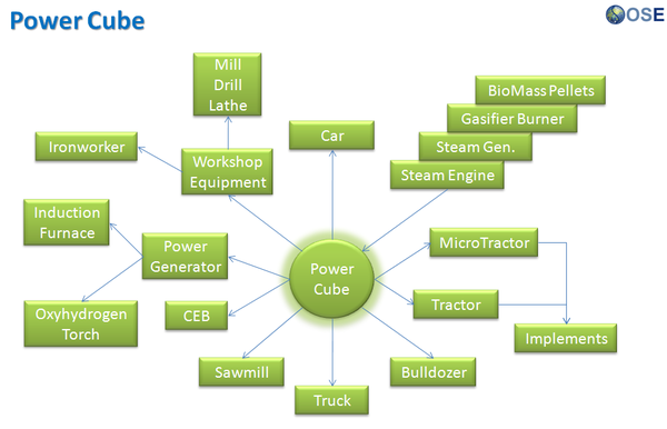
The current iteration of the power cube is an off-the-shelf gasoline engine, but the design is intended to be as power source agnostic as possible so that the power production can be readily changed. There will likely be many variations on the power cube design, but all fitting inside a similar size profile so that one GVCS machine can readily swap out one Power Cube for another.
| From | Uses | Creates | Enables |
|---|---|---|---|
|
Components
|
Video (Older Power Cube Designs)
- Introduction to the Power Cube Design (1 min 59 sec)
- Power Cube Complete (5 min 6 sec)
- Build Instructions (50 min 27 sec)
Development Status
Currently, the Power Cube is in development to product release, after numerous prototypes. See Status of Completion
See Also
- Announcement blog post
- Advanced Powercube Construction Set (A construction set that allows for easy swapping of powercubes in a powercube array)
- Open Source Motor/Engine Construction Set (A construction set for if we ever make our own motors/engines from scratch)
Useful Links
- A Wikipedia Page on Powerpack (Drivetrain) I just recently found this, it seems like a similar philosophy, although it doesn't use hydraulics I think. Still interesting though.
- A Wikipedia Page on Power-Eggs Same as the powerpack but for aircraft.
Links
| GVCS Home List | ||
|---|---|---|
| Home | Research & Development | Bill of Materials | Manufacturing Instructions | User's Manual | User Reviews | File:GVCS Home List.png | |
Overview
The Press Forge takes molten steel fresh from the Induction Furnace and presses it into useful forms.
Product Ecology
Uses
 Induction Furnace - Steel
 Hydraulic Motor - Press
 Power Cube - Power
See Product Ecologies for more information.
Components
- Press
- Die
- Feeder
- Roller
- Control Box
Status
Currently in the Research Phase of product development. Prototyping is dependent upon development of the Induction Furnace.
See Also
| GVCS Home List | ||
|---|---|---|
| Home | Research & Development | Bill of Materials | Manufacturing Instructions | User's Manual | User Reviews | File:GVCS Home List.png | |
Overview
A Rod and Wire Mill draws out molten metal into useful rods and wires. This is a subset of metal rolling, used to make shafts, rebar, thin rods, down to wire. Thin wire can then be produced by wire drawing through a die.
Details
Product Ecology
Made with
 Induction Furnace - Steel
 CNC Torch Table - Parts
Uses
 Induction Furnace - Metal Feed
 Power Cube - Power
Creates
- Rod
- Bars
- Wire
See Product Ecologies for more information.
Components
- Steel
- Rollers
- Hydraulics
- Controller Box
- Feeder
- Die
- Sensor
Status
Currently in the research phases. Prototyping is expected to begin after completion of the Induction Furnace
Subject Matter Experts are encouraged to Contact Us.
See Also
| GVCS Home List | ||
|---|---|---|
| Home | Research & Development | Bill of Materials | Manufacturing Instructions | User's Manual | User Reviews | File:GVCS Home List.png | |
Overview
A tractor implement that tills soil with blades via rotary action. It is a specialized form of Cultivator.
Field Use
During 2014 build of Faculty House:
Details
Cultivators stir and pulverize the soil, either before planting (to aerate the soil and prepare a smooth, loose seedbed) or after the crop has begun growing to kill weeds (controlled disturbance of the topsoil close to the crop plants kills the surrounding weeds by uprooting them, burying their leaves to disrupt their photosynthesis, or a combination of both). Cultivators are designed to disturb the soil in careful patterns, sparing the crop plants but disrupting the weeds.
Product Ecology
Uses
 Induction Furnace - Steel
 CNC Torch Table - Steel
 Hydraulic Motor - Power
 Power Cube - Power
 Tractor - Mounting
See Also
- Wikipedia: Cultivator
- Blog Post.
- Soil Pulverizer Industry Standards
- Steam Weeder
- Metallized Fabric as Ground Cover
- 100 Gallon Soil Slurry Mixer
| GVCS Home List | ||
|---|---|---|
| Home | Research & Development | Bill of Materials | Manufacturing Instructions | User's Manual | User Reviews | File:GVCS Home List.png | |
Overview
A sawmill converts felled logs from trees into green wood lumber. As a piece of the GVCS, it unlocks a range of well-established wood construction techniques.
To convert the green wood into finished dried lumber the cut boards are either air-dried or fired in a kiln.
Detailed Description
Product Ecology
| From | Uses | Creates | Enables |
|---|---|---|---|
|
Components
|
Status
The first Sawmill prototype is currently under construction as a part of the GVCS Rollout Plan.
See Dimensional_Sawmill_Prototype_I for in-progress videos.
Videos
See Also
- Sawmill - Design Rationale
- Sawmill Design
- Sawmill Analysis
- Research
- Sawmill Archive
- Cut-to-Length Logging
- Wood
- Forest
- Kiln
Links
Theo's Github Repository
https://github.com/Veradrix90/Dimensional-Sawmill
| GVCS Home List | ||
|---|---|---|
| Home | Research & Development | Bill of Materials | Manufacturing Instructions | User's Manual | User Reviews | File:GVCS Home List.png | |
Overview
A Seeder enables Tractor planting of any type of seed from small seeds like clover to large seeds such as potatoes.
Details
The goal is a general purpose workhorse device that meets OSE Spec for agricultural planting operations.
Product Ecology
Uses
 Induction Furnace - Steel
 CNC Torch Table - Steel
Works with
 Tractor - Mounting
 Power Cube - Power
 Spader - Agriculture
See Product Ecologies for more information.
Components
- Hopper
- Wheels
- Rollers
- Feed
- Filter
Status
The Seeder is currently being researched.
Videos
See Also
| GVCS Home List | ||
|---|---|---|
| Home | Research & Development | Bill of Materials | Manufacturing Instructions | User's Manual | User Reviews | File:GVCS Home List.png | |
Overview
Concentrated solar power (CSP) systems, are systems that use mirrors or lenses to concentrate a large area of sunlight, or solar thermal energy, onto a small area. Electrical power is produced when the concentrated light is converted to heat which drives a heat engine (usually a steam turbine) connected to an electrical power generator.
Details
Solar Concentrators
Categories
Product Ecology
| From | Uses | Creates | Enables |
|---|---|---|---|
|
Components |
Components
- Mirrors
- Tubes
- Boiler
- Turbine
Status
The Solar Concentrator is currently in the research phase of product development.
See Also (OSE Wiki)
- Zenman Energy
- Solar Fire
- Solar Collector Calculations
- Large Solar Basket
- 100 miles on each side
- Scheffler
External Links
| GVCS Home List | ||
|---|---|---|
| Home | Research & Development | Bill of Materials | Manufacturing Instructions | User's Manual | User Reviews | File:GVCS Home List.png | |
Overview
The spader is set of mechanical shovels that prepare soil for planting without causing a hardpan typical of rototiller tilling. Also called a "rotary spader".
Details
Agricultural Spader - This is the most advanced, but least affordable, method of soil preparation for planting. The spader is the mechanized equivalent of several digging shovels. It is operated by the power take off (PTO) behind a tractor. It operates like a rototiller, but with reciprocating spades. It is a superior method of soil preparation for planting - because, unlike a rototiller, it leaves better soil structure without creating a hardpan underneath the tilling layer. Moreover, the spader is capable of deeper tilling. This is the state of art in soil preparation, but few farmers are privy to it because of high cost - $5k for used machines. Our version will be driven by tractor hydraulics, eliminating costly gearing. The fabrication is not straightforward like a rototiller, as the spader spades ride on cams that are offset from a rotating axle. Effective fabrication strategy must be developed. Overall, this would help improve farmers' efficiency. The spader (and rototiller) are a one step soil preparation method - unlike plowing - which is typically followed by multiple disking or disking and harrowing.
They do not leave a "hardpan" due to the somewhat random action of the spades. Spaders are very expensive in north America as they are all made in Italy/Holland etc. (see links below). Inventing an open source spader would be a great achievment. They are a one pass type of implement, allowing easy working in of cover crops into the soil. Towing the spader behind LifeTrac would be easy as spaders are not a real load on the tractor/machine. All that is needed is a slow hydrostatic drive, but we have that covered.
Research
- The embedded video, showing a Celli spader with "shovels", is from a University of Vermont DVD (available here).
- Spader setup and operation - note 3rd pic down: it's the soil "pulverizer" after the spades. Spades dig first, "pulverizer" breaks up the clods and makes seed bed. Imants use a roller with curved tines instead. Does it all in one operation. Looks almost exactly like your tines on soil pulverizer.
- "Product Review: Spaders - These must-have machines help preserve soil structure". At the bottom of that page a reader suggests Imants spaders from Holland: "Imants produces a spader that achieves the same results based on a different mechanical approach". The Imants use circular "arms". They supposedly will leave a hardpan like a tiller (eventually). I'm sure they run smoother/longer though.
- Good spader video, shows the Imants final roller with tines. He discusses the mechanism up close.
- Another Imant in action.
Product Ecology
Uses
 Induction Furnace - Steel
 CNC Torch Table - Structure
Works with
 Tractor - Mounting
 Power Cube - Power
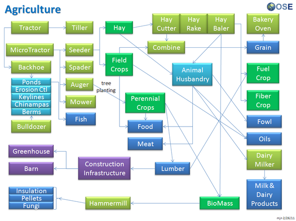
See Product Ecologies for more information.
See Also
| GVCS Home List | ||
|---|---|---|
| Home | Research & Development | Bill of Materials | Manufacturing Instructions | User's Manual | User Reviews | File:GVCS Home List.png | |
Overview
Steam Engine/Index - topical index to all steam engine pages.
The Open Source Ecology project seeks to develop a modular, scalable, open source steam engine capable of converting steam generated by a solar collector or boiler into power that can be used to generate electricity or drive machines found in the Global Village Construction Set.
Details
See Steam Engine Intro if you are interested in the current OSE steam engine project.
- Steam Engine Concept - a conceptual description of steam engines
- Steam Engine Breakdown -
- Steam Engine Specifications
- Steam Engine Specifications/Geometry
- Steam Engine/Terminology - terms used in steam engine technology
Steam engines take energy available as high pressure, high temperature steam and convert it into reciprocal motion. This motion can then be turned into rotational motion using a crankshaft. At the start of the twentieth century, steam engines provided power for farms, factories, and transportation. They were largely replaced by internal combustion engines. The Open Source Ecology project is interested in reviving steam technology to develop a modern steam engine to provide alternatives to engines driven by gasoline or diesel - which are becoming increasingly more expensive as our world passes the point of peak oil production.
Product Ecology
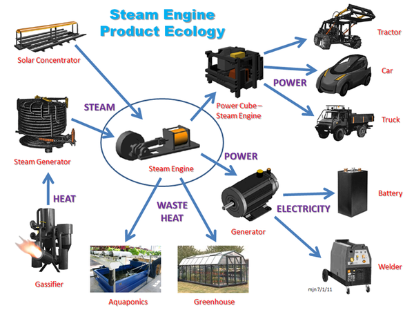
| From | Uses | Creates | Enables |
|---|---|---|---|
|
Components |
Status
The previous steam engine design is on hold pending evaluation of the Mounster Design. Marcin favors this design, but the intellectual property rights to it are unclear at this time. Subject Matter Experts or fabricators interested in making prototypes are encouraged to contact Mark Norton.
See also Hadden Engine
See Also
| GVCS Home List | ||
|---|---|---|
| Home | Research & Development | Bill of Materials | Manufacturing Instructions | User's Manual | User Reviews | File:GVCS Home List.png | |
Last updated Sep, 2015.
Overview
The Steam Generator is a device used to create steam by applying thermal energy to water.
Details
It can be used to power devices such as steam engines and steam turbines. Both of these machines convert expanding steam into rotational power, power that can be used to drive other GVCS tools or generate electric power. Excess or vented steam can also be used to heat a home or greenhouse.
Steam Generator Pages
Product Ecology
| From | Uses | Creates | Enables |
|---|---|---|---|
|
Components
|
Status
The Steam Generator is currently the Research Phase of Product Development.
See Also
Links
- 2016 - See Heat Exchanger Development
The LifeTrac Story 2012. from Open Source Ecology on Vimeo.
| LifeTrac | 
|
|---|---|
| LifeTrac III Home | Research & Development | Build It | User's Manual | Community Feedback |
Overview
LifeTrac is a low-cost, multipurpose open source tractor. It serves as a workhorse backbone for many of GVCS technologies. Prototype III stage has been completed, and field testing determined the need for Prototype IV prior to product release.
Featuring a modular design and detachable PowerCube units, it has the ability to rapidly switch between a variety of GVCS machines and/or Commercial Of-The-Shelf tools via the QA Plate. The machine is overbuilt with a focus on lifetime design and ease of repair.
Four hydraulic motors provide skid steer power to the wheels, and a chain tread system enables navigation of extreme terrain.
Join discussion at Hacker News - tractor discussion got the longest thread on Hacker News so far.
Details
Latest version of LifeTrac as of Jan. 2013 is LifeTrac IV - with Quick Connect Wheels and Bent Loader Arms, where III had straight arms and non-detachable wheel units.
Versions
Remote Repository
Distributed Collaboration
Distributed Collaboration is a way to manage the digital files that describe the machine in such a way that people all over the world can work together through the internet. The process is made up of three steps: definitions, projects and reports.
LifeTrac III Definitions The definitions are any files that specify what the pieces of the machine are. An experience fabricator would be able to make all the pieces from just these files.
LifeTrac III Projects The project(s) is a database that turns the definitions into steps which, if all accomplished, will result in a finished machine. At the moment, we're just using an existing project management program.
LifeTrac III Reports The report(s) is a polished document that compiles all the definitions and project steps together in a way that is easy to follow. Additionally, the report includes background, context and any other piece of information that is relevant to the machine but is not strictly related to making it.
Product Evolution
Use the Product Evolution tree below to learn about the different versions of the LifeTrac and how far they got in product development (shown in italics). Follow the arrows to see where branching occurs. The dashed outlined represents the most complete documented version to date and tested at FeF.
| Major Design Style | ||||||||||
|---|---|---|---|---|---|---|---|---|---|---|
| Articulated Design |

|

|

|
|||||||
| LifeTrac I Prototype 1 |
LifeTrac 5 | LifeTrac 6 | ||||||||
| Skid Steer Design |

|

|

| |||||||
| LifeTrac II Prototype 1 |
LifeTrac III Documentation |
LifeTrac IV Retrofit | ||||||||

| ||||||||||
| LifeCat 1.0 R&D |
Safety Concerns
No structural engineering analysis has been performed on the LifeTrac III or IV. If you choose to replicate this product you are doing so at your own risk and with this understanding. We will be performing analysis soon and will post those results as we get them.
There is also an email to OSE Europe mailing list describing some concerns about LifeTrac safety of use, and points out possible issues with: Frame, Steering, Brakes and Roll-Over Protection.
Product Ecology
| From | Uses | Creates | Enables |
|---|---|---|---|
|
Components |
Videos
| GVCS Home List | ||
|---|---|---|
| Home | Research & Development | Bill of Materials | Manufacturing Instructions | User's Manual | User Reviews | File:GVCS Home List.png | |
2013 Prototype
- 2013 Development page at Dozuki - http://opensourceecology.dozuki.com/c/Trencher_-_Modules
- 3D CAD - [36]
- YouTube playlist - [37]
- Images on Trovebox - [38]
- Test Video -
2012, Prototype I
A trencher is a piece of construction equipment used to dig trenches, typically for laying pipes or cables, or for drainage.
Think a chainsaw, but one that cuts into the earth.
Prototype I
Open Source Trencher. from Open Source Ecology on Vimeo.
Product Ecology
Created With
 Induction Furnace Steel
 CNC Torch Table Cutouts
 Welder
Used with
 Tractor - Mounting
Creates
- Trenches
See Product Ecologies for more information.
Components
- Motor
- Blade
- Teeth
- Housing
Status
The Trencher is currently in the Research Phase of Product Development
See Trencher Log
Videos
Example of a ripper with pipe laying attachment
See Also
Links
| GVCS Home List | ||
|---|---|---|
| Home | Research & Development | Bill of Materials | Manufacturing Instructions | User's Manual | User Reviews | File:GVCS Home List.png | |
Intro
A truck is a transportation machine that you can drive in order to move yourself, others, and stuff to wherever you can get with wheels. The difference between a truck and car is that trucks are stronger and have more dedicated space for stuff on the vehicle.
Documentation
If you're new to mechanical things, check out Mechanical Intro
Alternative Body Styles
Depending on the function of the truck, it could have a smaller body style. (Unless, it is intended for hauling large amounts of agricultural goods.) If a light duty vehicle is all that would be necessary in many situations, then a more efficient size might be better.
There are a couple examples of small body styles that are common to the rest of the world but not in North America. First is the coupé utility (basically the same as the Chevrolet El Camino), known as the Ute in Australia and New Zealand. Second the minitruck from Japan, as known as the Kei truck, which are being imported to the United States as light duty off-road vehicles in some rural areas. In both Australia and Japan, vehicles are right-hand-drive. Though, it might be legal to operate a RHD vehicle on US roadways, there is the issue of practicality.
https://en.wikipedia.org/wiki/Ute_(vehicle)
https://en.wikipedia.org/wiki/Kei_truck
A small modular design with standardized parts is probably more cost effective and still allows for vehicle type options.
Concepts
More Concepts
Concepta
Maintenance Concept Text
Pneumatic
Tire Air Pressure
Hydraulic
Engine Oil
Coolant
Transmission Fluid
Brake Fluid
Windshield Washer Fluid
Mechanical
Tires
Brake Pads
Windshield Wipers
http://www.carbibles.com/maintenancetips.html
Engines have a lot of moving parts that rub against each other and create friction. The friction generates a lot of heat. When plastics get hotter and hotter, they get softer and eventually melt. When metals get hot, they get softer, which accelerates wear, and if hot enough, metals melt too. So cooling the engine is important. The engine is essentially a complex hulk of metal, so pumping water through it will cool it down. But water boils and freezes too easily- if the water turns into a gas, then it loses a lot of cooling ability- in other cases, a lot of pressure (from gaseous expansion or ice formation) will crack and break the solid parts of the cooling system (and the engine). So adding substances (like antifreeze) keeps the coolant system working in hot and cold conditions.
Another way to solve the heat problem is to stop friction in the first place. Lubricants are substances that have very low coefficients of friction so they generate very little thermal energy when rubbed together. By applying lubricants to the moving parts of an engine, less heat will be generated.
Car Maintenance - Scotty Kilmer's Youtube Channel
Maintenance Concept Videos
More Concepts 3
Gear Dimensions and Terminology File:Geardimterm.pdf
Gear Types from Engineer's Edge
More Concepts 3
text
4 Wheel Drive
4 Wheel Drive Explanation at Wikipedia
Leaf Suspension vs Coil Spring
Leaf vs Coil Comparison at JP Magazine
Leaf vs Coil Comparison at eHow
Cargo Bed Size and Payload
Towing Interface and Capacity
Manual vs Automatic Transmission
Ground Clearance
Fuel Efficiency
http://en.wikipedia.org/wiki/Auto_maintenance
Fuel for regular operation
Engine oil for lubricating
Oil Filter Replacement
Coolant for cooling
Filling Radiator Fluid, Video at Youtube
Coolant Filter Replacement
Brake Pad Replacement
Tire Replacement
Overview
http://opensourceecology.org/wiki/Truck/Research_Development
The Open Source Truck is a heavy off-road vehicle capable of equipping many pieces of equipment used on the Tractor, and transporting heavy loads long distance. The Open Source Truck project is currently in the research phase.
Detailed Description
Goal specifications
- Open Source Truck Concept - similar to Mercedes Unimog:
- Top speed of 60 mph
- Equipped with suspension
- Capable of handling extreme off-road conditions
- Equipped with front and rear power take-off, hydraulic take-off, and quick attach mounting plate for hydraulic heavy and rotary equipment such as backhoe, loader, power generator, hammermill, pelletizer, and any agricultural, utility, and construction equipment that is already avialable for the Tractor or Microtractor
- Dual utility for agricultural and transportation uses
- Hydraulic drive
- Quick attach Power Cube
- 27-270 hp models
- Eventually powered with Modern Steam Engine
Product Ecology
| From | Uses | Creates | Enables |
|---|---|---|---|
|
Components |
Status
The Open Source Truck is currently in the Research phase of product development.
See Also
| GVCS Home List | ||
|---|---|---|
| Home | Research & Development | Bill of Materials | Manufacturing Instructions | User's Manual | User Reviews | File:GVCS Home List.png | |
Main > Energy > Power quality
Overview
A Universal Power Supply forms the backbone of an off-grid electrical system for powering machines and power electronic devices such as the induction furnace.
Updates
- See Universal_Power_Supply Requirement for 2019 version.
- Initial prototypes:
Definition/Concept
This is a combination inverter, converter, pulse-width modulation current controller, and high frequency power supply for applications from off-grid power, charge controllers, to power supplies for welders, induction furnaces, and plasma cutters.
A large range of power electronic devices is desirable within the infrastructure of communities. Having an individual power supply for each is redundant and expensive. A modular UPS construction kit is desirable as an analogue to the 'industrial-strength Lego' that we have already demonstrated for heavy mechanical hardware infrastructures.
Rectifiers
Rectification is the conversion of AC to DC. A universal power supply would require one or two rectifying stages: one at the AC input to provide DC for the voltage converter, and another if the voltage converter is a proper Active PFC converter, which produces PWM shaped output.
Rectifiers can be either passive schottky diode bridges, or active (IC-controlled) MOSFET H-bridges. Passive ones are cheaper, and ultimately more efficient for very high currents, while active ones are superior for low-medium-and-maybe-high currents yet more expensive. This design choice affects price, producability and simplicity.
In either case a rectifier stage requires power packaged components and a heat sink. The size of the heat sink is a function of the current, which is higher at low voltages for a given output power. Questions for the specification is how much power the device should be able to deliver from a 12V source (first rectifier in the case of voltage up-conversion) and to a load at 12V DC output (second rectifier if present).
Voltage Converters
Inverters
An inverter is an electrical device that converts DC voltage from batteries to AC voltage for off-shelf electrical tools and appliances.
Off-the-shelf inverters have about a 2 year lifetime, and 5-10 year lifetime for higher quality models. Lifetime design inverters with plug-in replacement components are required for sustainable communities which use battery storage as a component of their electricity infrastructure. One of the few other feasible, non-battery, non-fuel energy storage may be via heat storage coupled to thermoelectric generators, or possibly thermal storage via phase-change salts and heat engines.
Product Ecology
| From | Uses | Creates | Enables |
|---|---|---|---|
|
Components |
Status
OSE is recruiting subject matter experts with experience in inverter design. Those with relevant experience are encouraged to Contact Us
Adjustable Power Supply v18.08 is in development
See Also
- Concept
- Inverter
- Electricity
- Charge Controller
- Problem Statement
- Power Electronics Construction Set
- http://preciodelorohoy.wordpress.com/ - Information about power supply
| GVCS Home List | ||
|---|---|---|
| Home | Research & Development | Bill of Materials | Manufacturing Instructions | User's Manual | User Reviews | File:GVCS Home List.png | |
| ||||||||||||||||||||||||||
Development
Overview
The Universal Rotor(UR) is a standardized, heavy duty, modular, scalable rotor for utility, construction, and manufacturing purposes. The current iteration inolves a triple interface mount that allows for various tasks (work) to be accomplished by harnessing the high rotational torque and speeds generated by a hydraulic motor (or electric motor, etc). This is a fundamental component for any GVCS machine that uses a motor. It provides modularity, redundancy, scalability and represents a significant cost reduction by being able to use only one motor to power many machines. Examples are: Attaching the wheels to Lifetrac and powering them; a mower, auger or slurry mixer for Lifetrac; the saw blades on the Saw Mill. Attaching a lathe chuck and adding the 2" Universal Axis with Universal Controller turns it into a CNC lathe. It can be used to drive heavy slow rotors, such as a plastic shredder, pelletizer, or with geardown - a rock grinder. It connected to rollers, this can drive metal rolling equipment.
Build
Details
This triple interface that allows the UR to harness motor power has 3 interfaces which each have 2 sides to it. The following are the three interfaces with the 2 sides of each interface in parenthesis:
1) Anchor Interface: (Receiver & Attachment)
Is the stationary side of the interface and serves to 'anchor' the UR to a solid object. This is done by connecting/inserting the Attachment on the UR to the Receiver on the solid object.
-Allows the shaft(tool) to be mounted at multiple angles in relation to the machine. This makes the UR useful for vertical shaft applications like an earth auger or mower and horizontal shaft applications like a wheel trencher or wheel drive that powers the LifeTrac. This can be accomplished with a single square tube which is rotated 90 degrees and reattached.
-Another axis of rotation can be accomplished by adding multiple tubes to either the receiver side of the interface at angles to the primary one. It could also be accomplished by using an angle adapter tube.
2) Power Interface: (Motor & Mounting Plate)
Mounts the motor to the mounting plate which is part of the UR's structure. In addition to how the motor attaches, this interface also considers the space that various motors would need and ensures that the rest of the UR structure nor the machine it is attached to doesn't interfere with the space need for motors. Additionally, space for motor removal and the connection and protection of hydraulic lines needs consideration. There are four common motor mount styles: Face, Wheel Motor(body) Tail, Base. The focus of the UR will be face and wheel motor mounting for hydraulic motors. For face mounting the UR will utilize SAE hydraulic motor mounting dimensions since the GVCS hydraulic motor will likely adopt these and SAE motors are currently being used by OSE and readily available. Wheel Motor Mounting dimensions are less standardized. In either case by starting with one of the largest SAE face mounting patterns, adapter plates can be bolted to that pattern to accommodate smaller face mount and wheel motors.
3)Tool Interface: (shaft connection & tool connection)
Connects the rotating shaft of the motor to the tool to be rotated. There might be adapters for different applications. For example a tire rim on the LifeTrac might bolt to the same mount as an 8' diameter wheel trencher. But that might be to large mount for an auger or a 16” cold saw blade. The primary mount needs to be sufficient to handle the forces for all applications, and then smaller adapter mount attached to it. The primary mount should be as compact as possible but still quickly attachable, perfectly concentric and have zero slop. If a wheel style mount is used, there are two types, hub concentric(w/flat lug nuts) and stud centric(with tapered/cone lug nuts)
1,2&3) All three interfaces must individually be:
-Scalable in thickness or dimension for applications with higher forces
The Universal Rotor as a whole must be:
-Withstand extreme radial, axial and twisting(in relation to the motor shaft) generated by all the applications for which it will be used for.
-Light as possible to be managed by hand
-Compact
Other Considerations:
1) Accomodating for gearing and multiple motors
Because there may be a limit to the amount of power or speed that available motors produce, gearing or the use of multiple motors may be needed when the tool requires more power or speed. For gearing with a single motor this can be accomplished by breaking the direct connection between the motor shaft and the tool and routing the power flow thru a gear reduction (chain & sprockets) first. Or additional motors could be added by keeping a direct connection between the tool and motor but mounting a 2nd motor and connecting its shaft to the shaft of the primary motor via chain. However, if the speed and power of the motor is suitable for the application it is best to have a straight connection to the tool.
Decisions:
1) Wheel Motors(bearings built in) or Jack Shaft(with auxiliary bearing support structure)?
Due to the wide range of applications, the UR needs to handle high axial and radial forces. Wheel motors have larger bearings then standard hydraulic motors to resist these much higher forces. Wheel motors are available commercially that will handle the radial and axial loads of all current GVCS applications. However wheel motors are low speed. High speed motors don't usually have such large bearings. While generally you don't need large bearings while doing high speed operations, an accident, such as hitting a tree stump with a high speed mower blade may damage a motor with smaller bearings. Adding a separate shaft(jack shaft) that is supported by separate bearings between the motor shaft and tool effectively isolates the motor shaft and bearings from any radial forces, as well as axial forces if properly designed. This is the design currently being used on LifeTrac III and the MultiAuger. The current design on the LifeTrac is excessive in length and has some proven and suspected issues. A much shorter and simpler jack shaft setup should be possible that is more comparable to a wheel motor in size. If a jack shaft setup is chosen as the primary UR setup, it should be designed so that only wheel motor can be used instead with minimal variation(or none) for replicators who choose to do so.
The current quick connect wheel assembly with the jack shaft and auxilary bearings was a necessary component when the LifeTrac was powered by the original weaker drive motors. However during the redesign, new 15,000 Inch Pound Motors were purchased which are actually wheel motors that have a much higher carrying capicity which means the whole jack shaft assembly might not even be necessary as the motor is designed to handle up to 11,000 of radial load per the specs provided by the manufacturer. It has already been proposed by Marcin that the wheel connect be redesigned to address several issues, but in reality, it can actually be completely ommited without having to purchase additional motors.
Comparison:
Wheel Motor UR Advantages:
-Much more compact, lightweight, cheaper and very quick to build
-Sealed & lubricated bearings
-Industry Proven
-Less parts to break or wear out
Auxiliary Bearing UR Advantages:
-Can remove the motor with out disconnecting the tool(or the tire when used as wheel drive)
-More motor choices (especially rpm)
-Can use a gear reduction or multiple motors much easier
2) Tapered or Roller Bearings?
If a jack shaft with auxiliary bearings are to be used, will it use tapered bearings to resist axial thrust or just thrust washers? Thrust washers are not good, especially if the tool is hanging, being pushed on(ie. Auger) or anything with constant side loading. The only reason not to use tapered bearings is because they are harder to make and mount out of raw steel and if a suitable off-the-shelf setup might not be found in the mean time They also require preloading of the two opposed tapered bearings against each other by means of a threaded shaft or a press fit. One source might be preassembled “4x4 truck hubs” as found on ebay. A tapered bearing solution will almost always be more compact and robust.
Before spending much time on one particular design, it will help to imagine that design being used in each of the applications that the UR is to be used in.
Applications with the LifeTrac for the UR:
Other GVCS machines with UR applications:
Product Ecology
Uses
 Induction Furnace - Steel
 CNC Torch Table - Parts
 Tractor - Mounting
 Power Cube - Power
 Hydraulic Motor - Power
Mounts
- String Trimmer,
- Tree Planting auger,
- Lathe,
- drill press,
- soil line cutting rotor,
- honey extractor.
- Trencher
Status
The Universal Rotor is currently in the prototyping phase of product development.
The hydraulic motor is interchangeable, and so far, a 32 cu in and a 6 cu in motors have been used which have a quick mounting plate with 2 3/4" bolts for hold-down. The assembly can be mounted either horizontally or vertically by bolting to a back plate accordingly.
Future prototype designs aim to improve structural integrity, increased ease of mounting for LifeTrac, and improved interchangeability of motors.
Actions are logged in Universal Rotor Log.
Links
- Universal Rotor Construction Set
- Universal Rotor 2 - Modular Wheel Units - are one implementation of the Universal Rotor. Also used in track drive.
- Deka-kW VAWT Wind Turbine - another implementation of the Universal Rotor
- Blog Post
- CAD
- Institution of Engineering and Technology
| GVCS Home List | ||
|---|---|---|
| Home | Research & Development | Bill of Materials | Manufacturing Instructions | User's Manual | User Reviews | File:GVCS Home List.png | |
Overview
The Welder enables all the wonders of welding, a fabrication process that joins metal pieces together.
Details
Welding is often done by melting the workpieces and adding a filler material to form a pool of molten material (the weld pool) that cools to become a strong joint, with pressure sometimes used in conjunction with heat, or by itself, to produce the weld. This is in contrast with soldering and brazing, which involve melting a lower-melting-point material between the workpieces to form a bond between them, without melting the workpieces.
Product Ecology

Uses
 Universal Power Supply - Power
 Rod and Wire Mill - Welding Wire
Used by
See Product Ecologies for more information.
Components
- Wire Feed
- Spooler
- Tensioner
- Transformer
- Welding Wire
- Control Box
- Handle
- Nozzle
- Sleeve
- Case
Status
The Welder project is currently in the Research Phase of product development.
See Also
| GVCS Home List | ||
|---|---|---|
| Home | Research & Development | Bill of Materials | Manufacturing Instructions | User's Manual | User Reviews | File:GVCS Home List.png | |
Overview
The Well Drilling Rig enables the construction of water wells. Water is crucial for human and animal consumption, washing, irrigation, and industrial processes. Access to clean drinking water is one of the key challenges facing many countries today. Addressing this need with the GVCS has the potential for far reaching impact.
If this machine plans are changed little to "General Drilling Rig" it can be used also mining purposes, to drill & blast caves, make bolt holes, drill water and geothermal wells etc. There can be two changeable drill heads. One for bigger holes (compressed air driven) and second hydraulic driven (fast) for smaller holes. And modified LifeTrac may carry them. Modified Backhoe offer enough movement for drill head tool.
Description
Well drilling can be broken down into three basic phases:
- breaking up the rock/soil in the well column
- removing the cuttings from the well column
- stabilising the well column and preparing it for production.
Breaking Breaking of rock/soil to produce cuttings is achieved by a cutting tool, either a rotating drill bit or a raised and dropped 'chisel-like' device; for the GVCS well drilling rig we will likely employ the rotating bit design as it is a much more common method of well preparation. The bit is rotated by attaching it to the end of a long series of pipes connected together called the drill string, turning the drill string turns the cutting bit.
Pumping Once the bit has cut up the rock/dirt it needs to be lifted up out of the well. The most common way of doing this is to pump water/mud down the center of the piping that makes up the drill string, and letting it flow out the end of the bit. By continuously pumping more drilling mud into the well, it eventually fills up and the only place left for the mud to go is to be pushed up to the top of the well and spill over the side, carrying the cuttings along with it. This flow of mud and broken up rock spills over the top of the well and is sent to a small settling pond where the rocks and sand settle out of it. After some time in the settling pond the mud is recycled by the mud pump and pushed back down the well again to pick up and remove more cuttings allowing the well to be contiuously drilled deeper and deeper, stopping only to add new sections of drill string.
Stabilizing After the well is drilled to the desired depth it must be finished and put into production. The drill string is withrawn from the well, but the well is left full of water/drilling mud to prevent the sides from caving in until the well is finished. After the drill string is out the casing pipe is slid into the well to prevent caving in of the sides. Once this is done, the drilling mud is removed from the well column leaving it empty. At this point a water bucket or temporary well pump is placed in the well and as much water as possible is drawn up for a test period of 1 to 3 days to clean out any remaining drilling mud and stabilize the aquifer for production. Also during this time the water extraction rate is measured to verify that it is worth continuing to finish the well (poor producing wells may have the casing withdrawn and be re-drilled at a more favorable location). Once the well is shown to be a producing well it is capped with a cement cap, and the water pump is installed making the well operational.
Product Ecology
Made with
 Induction Furnace - Steel
 CNC Torch Table - Parts
 Power Cube - Power
 Hydraulic Motor - Drill, Ram, Vacuum Pump
Uses
 Hydraulic Motor - Pump
 Power Cube - Power
 Cement Mixer - Cement Cap
Creates
- Water Wells
Components
- Steel
- Drill
- Pipe Casing
- Drill String
- Hoses
- Mud Pump
- Vacuum
Status
The Well Drilling Rig is currently in the research phase of product development
Internal Links
External Links
- GVCS Research
- HydroMissions - Products
- Practica Foundation - Publications
- Drilling Fab
- Life Water - Technical Library
- EMAS - Vimeo: Well Drilling Videos
| GVCS Home List | ||
|---|---|---|
| Home | Research & Development | Bill of Materials | Manufacturing Instructions | User's Manual | User Reviews | File:GVCS Home List.png | |
Overview
The Wind Turbine is a machine that converts mechanical kinetic energy of the wind into electrical energy. As a part of the GVCS it enables the generation of clean, renewable power.
Details
Small wind turbines are currently the main class being considered as a community-scale solution for power. These turbines may be as small as a fifty watt generator for boat, caravan, or miniature refrigeration unit. Small units often have direct drive generators, direct current output, aeroelastic blades, lifetime bearings and use a vane to point into the wind.
Product Ecology
| From | Uses | Creates | Enables |
|---|---|---|---|
|
Components
|
Status
Open Source Ecology Europe and -Germany are working on a prototype VAWT design: Germany/Wind_Turbine. Research and development is currently concentrated at TiVA, a tiny wind turbine prototyping platform. With this very small turbine, we can easily change parts, try out new ideas and increase the quality of the design on a small scale in a fast and inexpensive way.
The wind turbine is currently in the Research phase of product development.
There are a wide number of Open Hardware turbines, that are currently under consideration for adoption/consideration as a part of the GVCS.
portable wind turbine that can fit in a tube; wind lens.
OS Projects
- AirEnergy 3D [39]- A 3D printed, opensource, mobile wind turbine.
- SolarFlower [40]
- Zoetrope [41]
See also
Wikipedia
- Wikipedia: Wind turbine
- Wikipedia: Wind turbine design
- Wikipedia: Small wind turbine
- Wikipedia: Open design
External links
Main > Energy > Wind energy
- Pages with ignored display titles
- EN
- Product Ecology
- Pages with broken file links
- GVCS
- GVCS Home List
- RepLab
- Materials
- Chemical engineering for OSE use
- Backhoe
- Earth moving
- Bakery
- Food and Agriculture
- Vélocar
- Hint
- CEB Press
- CNC Torch Table
- Dairy Milker
- Energy
- Hydraulics
- Induction Furnace
- Specifications
- Metalworks
- Digital Fabrication
- Hole Puncher
- CNC Machine
- CNC
- CNC Multimachine
- Power Cube
- Solar Turbine
- Steam Generator
- Farm equipment
- Design Rationale
- Power quality
- Electronics
- Water
- Wind
- Wind turbines
- Wind energy
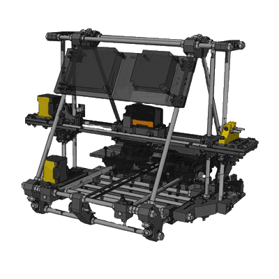





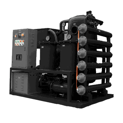
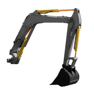
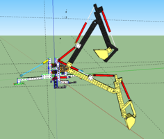

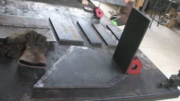
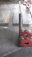
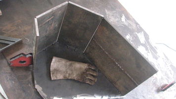
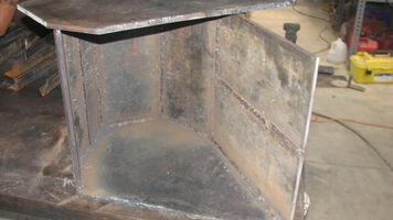
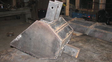
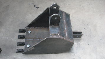
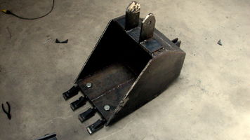
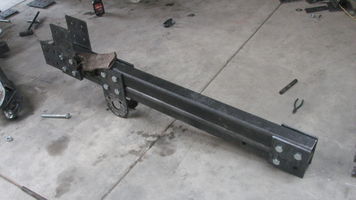
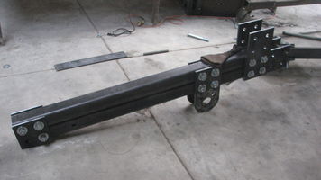
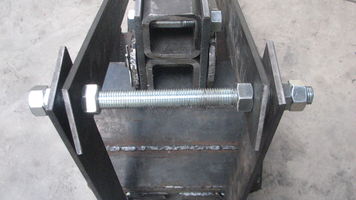
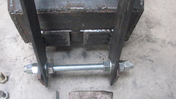
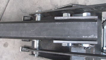
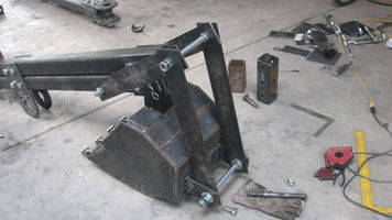
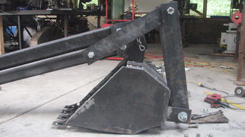
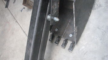
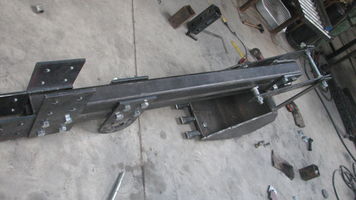
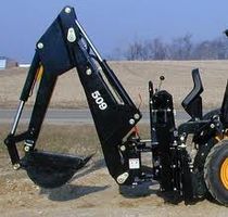
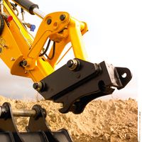
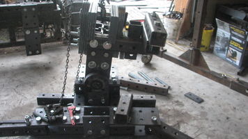
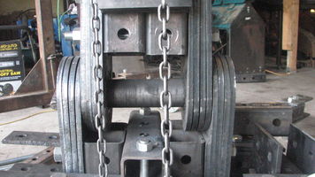
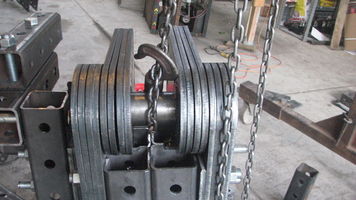

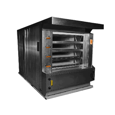

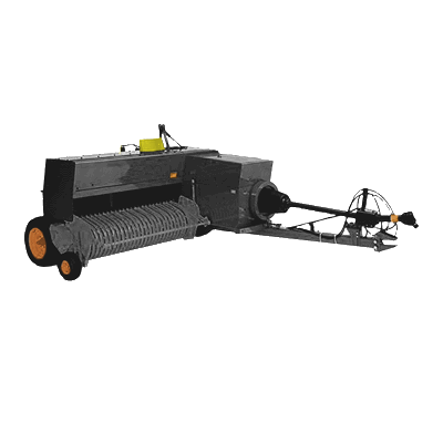


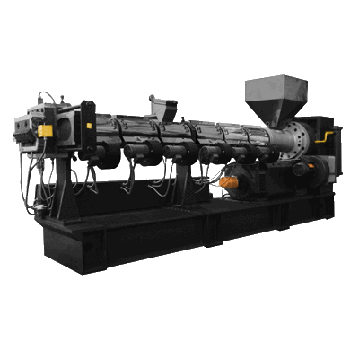

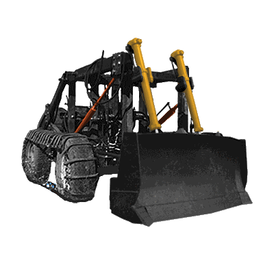
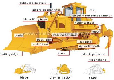
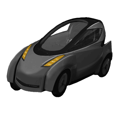


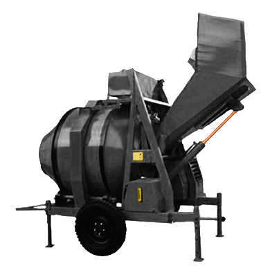
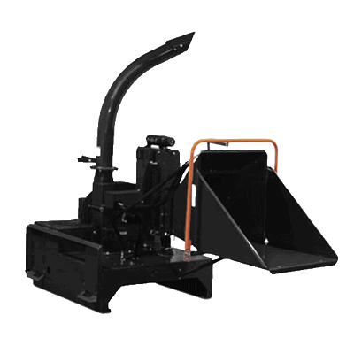

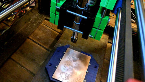
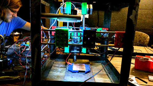
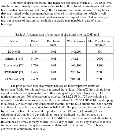
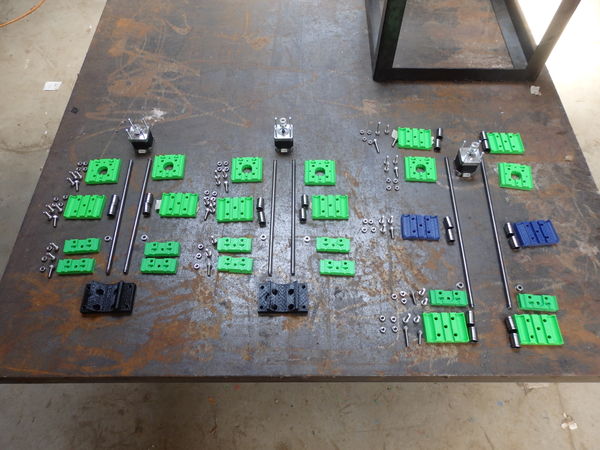
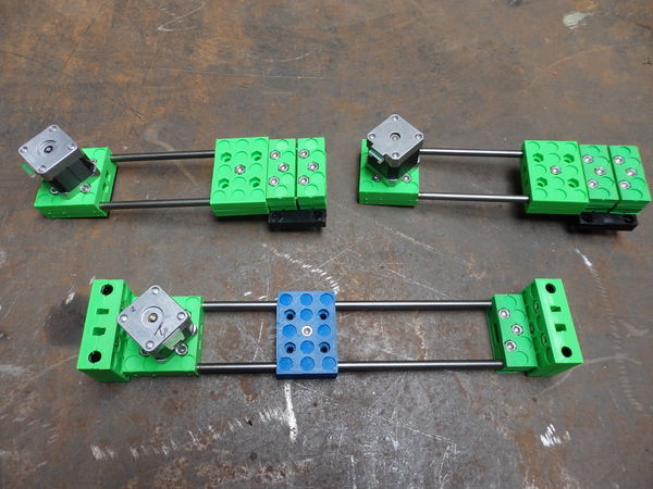
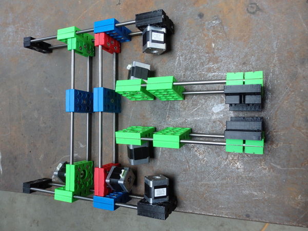
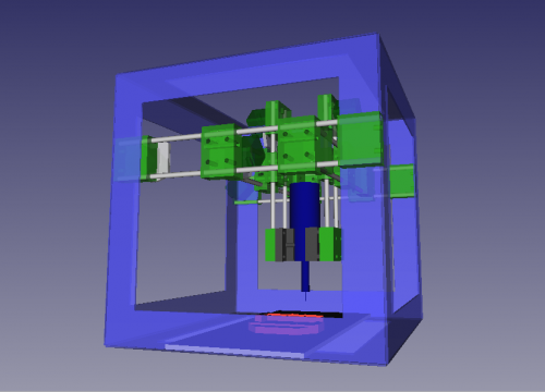
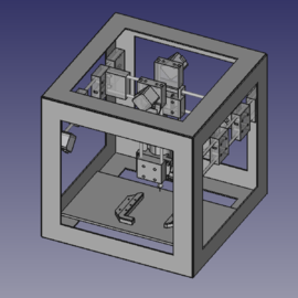
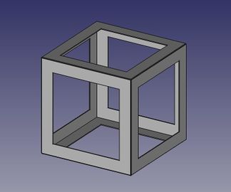
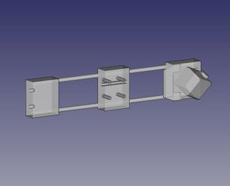
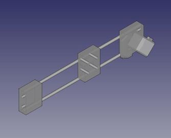
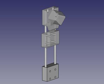
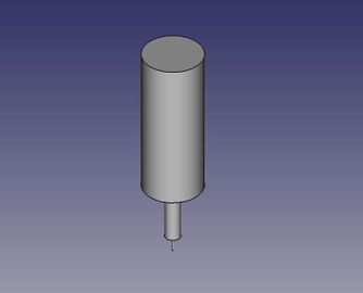
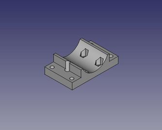
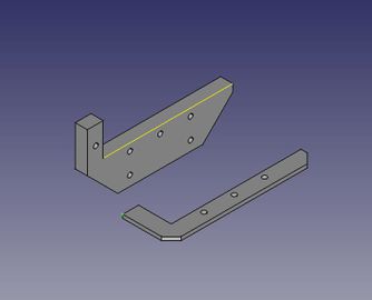
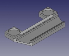
![16x carriage piece: [[1]]](/images/thumb/6/65/Universal_axis_carriage_side.jpeg/216px-Universal_axis_carriage_side.jpeg)
![16x idler piece short: [[2]]](/images/thumb/d/d4/Universal_Axis_Idler_piece_short_complex.jpeg/222px-Universal_Axis_Idler_piece_short_complex.jpeg)
![12x motor piece: [[3]]](/images/thumb/9/91/Universal_axis_motor_side_complex.jpeg/216px-Universal_axis_motor_side_complex.jpeg)
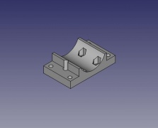
![PCB holder: [[4]] and File:D3dcnccm PCB holder.stl](/images/thumb/6/6d/PCBholderaccurate.jpeg/229px-PCBholderaccurate.jpeg)

